Hello PB2,
Yes I saw that thread before starting all this that's actually what gave me the idea. Only I myself am not experienced enough to go modifying that design and as it is it doesn't work.
I installed the mx50 kit already so I'm trying to make that work.
At the moment I'm still stuck with this hum : .
.
This is with oscilloscope on 5mV/div and 5ms/div. Does this look like hum caused by poor wiring or is there something else going on ?
I haven't been able to work on it sins the last message I posted here.
Yes I saw that thread before starting all this that's actually what gave me the idea. Only I myself am not experienced enough to go modifying that design and as it is it doesn't work.
I installed the mx50 kit already so I'm trying to make that work.
At the moment I'm still stuck with this hum :
.This is with oscilloscope on 5mV/div and 5ms/div. Does this look like hum caused by poor wiring or is there something else going on ?
I haven't been able to work on it sins the last message I posted here.
Last edited:
In gnd on the mx50 board is connected to the ground trace also going to the volume pot and then back through the switches and phono preamp board to the chassis at the inputs. This seems pretty standard. I tested for continuity and all the connection (although taking a very long path to chassis) are making good contact.
Last edited:
I'm not familiar with the STK8050 but here is a similar thing for the STK0050, see the
picture toward the bottom of the first page:
STK-0050 replacement for SX-780 and others | Audiokarma Home Audio Stereo Discussion Forums
Here is the PC board and hardware kit on ebay:
STK-0050 Module W/ Power to operate sets up to 85 Watts (Open Source) | eBay
Perhaps it could be adapted for the STK8050?
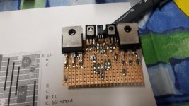
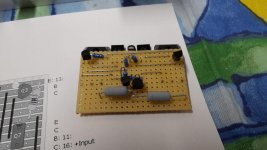
For those this might interest, this works perfectly as is in the Technics SU-V4.
I just had to drill 4 extra holes in the heat sink, remove some components used for the synchro bias circuit and connect. The results are pretty impressive, it's absolutely stable, gets a little more power output that the original stk, and allows you to keep the tone controls in the feedback loop. Sound is in my opinion superior to the stk's but that might just be because I got it working.
Some pics :
View attachment 676953
View attachment 676954
View attachment 676955
Nice work and good solution for this amp!
Nice!
Is it something that you will share or is a commercial solution?
This module isn't at all designed by me, you can find a thread about it here : STK-0050 replacement for SX-780 and others | Audiokarma Home Audio Stereo Discussion Forums
I bought this kit : STK-0050 Module W/ Power to operate sets up to 85 Watts (Open Source) | eBay
It does not include the components but there is a detailed list.
The only credit you can give me is installing it in The Technics SU-V4 (this, from what I know, hadn't been done before) and testing the result.
There is a link to the Mouser project BOM in the thread.It does not include the components but there is a detailed list.
There is a link to the Mouser project BOM in the thread.
Rick are you the seller of the board on ebay?
Hi Pete,
No I am not, another fine AK member is the seller because he has a source to fab the aluminum plate which he includes with the pcb and some metric hardware.
I stated in the AK thread that I did not want to profit from the pcb, my contribution to the community, so I released the pcb fab files into the public domain for anyone to have a pcb made. I put up the Mouser project BOM link to order the parts.
Rick
I'd like to give this a new try. I have an SU-V4A with failed STK8050. I opened it and am now in the progress of choosing the right parts for building a STK8050 with discrete components which works as a direct replacement.
The chinese copies get more and more expensive and fail most of the time. They seem to be missing the emitter resistors at the power transistors.
At the moment I have these open points:
- Measuring the emitter resistors at a working STK8050
- Choosing usable transistors
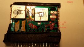
- Not sure if the temperature compensation transistor is actually one transistor or a darlington transistor. However it is only one compnent in the STK.
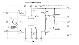
There are pictures of the broken STK and the schematics.
Shared album - Christian Lehner - Google Photos
Any help would be great.
Regards
Christian
The chinese copies get more and more expensive and fail most of the time. They seem to be missing the emitter resistors at the power transistors.
At the moment I have these open points:
- Measuring the emitter resistors at a working STK8050
- Choosing usable transistors
- Not sure if the temperature compensation transistor is actually one transistor or a darlington transistor. However it is only one compnent in the STK.
There are pictures of the broken STK and the schematics.
Shared album - Christian Lehner - Google Photos
Any help would be great.
Regards
Christian
Well, it looked promising. I connected my STK replacement to a channel of which I knew it was working with a working STK. I monitored the voltage over an emitter resistor and switched power on. The speaker relay turned on an I measured about 20mV. A few seconds later the voltage began to rise until I switched off at about 80mV. I then checked if any of the parts got warm, but they didn't. So I tried again.
Immediately I got smoke from my STK and the main fuse blew. Both power transistors are completely shorted now and I have no idea what happened.
Maybe I should just throw this Technics away and never get one again.
Immediately I got smoke from my STK and the main fuse blew. Both power transistors are completely shorted now and I have no idea what happened.
Maybe I should just throw this Technics away and never get one again.
Well, it looked promising. I connected my STK replacement to a channel of which I knew it was working with a working STK. I monitored the voltage over an emitter resistor and switched power on. The speaker relay turned on an I measured about 20mV. A few seconds later the voltage began to rise until I switched off at about 80mV. I then checked if any of the parts got warm, but they didn't. So I tried again.
Immediately I got smoke from my STK and the main fuse blew. Both power transistors are completely shorted now and I have no idea what happened.
Maybe I should just throw this Technics away and never get one again.
I don't understud.
Is the replacement a fake STKXXX?
If so what other would be expected than smoke?
Last edited:
I can really recommand using the kit we were talking about earlier in this thread, it worked absolutely perfectly on my SU-V4. You'll have to drill 2 extra holes on each side to mount to the heatsink, remove all the components related to the synchro bias circuit (I can give you the references if needed) and wire it up to the board.
- Home
- Amplifiers
- Solid State
- Build STK8050 equivalent