Hi Depaj,
I don't have the schematic in front of me, so I can only ask you. Are the tone controls using an op amp for gain, or the output stage (like the Yamaha A-500 for example)?
If they use an op amp, no problem, you don't have to do anything. If they don't, then you are looking at the amplifier as a tone control gain stage. Then you should probably us an op amp instead of the amplifier. You just take the signal from the output of the op amp. Of course you could always delete the tone controls all together.
-Chris
Ignore IC303. It's a DC servo.
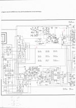
The SVI chip is an output stage only and it is driven by a discrete voltage amplifier stage using the DC servo. The tone controls are in the feedback loop (uncool). So they hampered the amplifier stage with a tone control circuit built in to save $$. Not many $$ either.
Go ahead and build it the same way. You're using the same voltage amp stage so the output stage change should have a lower effect on stability than as if it was the entire amp on a chip. This still means that you watch out for oscillation with your scope.
-Chris
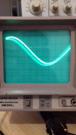
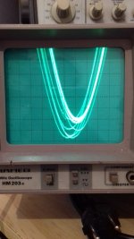
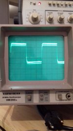
I've swapped one complete amplifier section (from R301 to the output of the stk) with the kit I ordered and it works great. Relay kicks in after about 5 seconds, and I have a nice and clean sine wave. now for the tone controls, I disconnected the feedback resistor on the side connected to the diff amp, fed it through the tone controls and back in where the other leg of that resistor used to be. The tone controls work as they should but as you predicted the top and lower parts of the square wave are a little shaky but it doesn't look like it's oscillating (with a normal volume level I didn't notice it on the oscilloscope but when I turned the sensibility up and the volume of the amp down it became visible).
Back with some news, I started with just one channel and it turns out to be working really well without the tone control, protection circuit works perfectly, as does the power meter. Now with the tone controls in the feedback it does work and the controls affect the square wave as they should but as predicted the top and bottom part of the wave are somewhat shaky. a slight adjustment might be enough cause as soon as I turn the volume up a bit and thus lower the sensibility of the oscilloscope it becomes rapidly invisible. Would it help to leave the first differential stage in there and hook it up
to the mx50 like this or will that completely mess things up ? :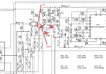
to the mx50 like this or will that completely mess things up ? :

Hi Depaj,
Leave the diff pair alone. Why not try and put some resistance in series with each end of the pot to restrict it's range a little? That will probably solve the instability issue you are seeing. Personally, I'd restrict the tone controls to a range of +/- 6 dB. Any more than that and the tone controls are being misused. Just a thought.
-Chris
The diff pair Q301 is out for now so i'll leave it that way. It would seem that the su-v4 has absolutely no pre-amp section so coming straight from the output of the volume pot, right in to the mx50 doesn't give me enough gain to get to 50W unless I crank up the function generator all the way. I now have the two amps installed, one with the tone control feedback, one without. The one with tone control has a much higher gain : I easily get the 50w where the other one is still at 5W. I checked but on both the resistance from output to inverted input is 10K, where does this raise in gain come from ? Also the one with tone control has a pretty audible hum to it. But that might just as well be the wiring this setup requires.
By end of the pot I suppose you mean the pin connected to the wiper ? What kind of resistance am I looking for in order to shave off 4db ?
By end of the pot I suppose you mean the pin connected to the wiper ? What kind of resistance am I looking for in order to shave off 4db ?
Last edited:
Hi Depaj,
Your tone controls probably give you another ~ 20 dB worth of gain (10 X the voltage amplification). Someone can simulate it if they want. The gain comes about due to the additional attenuation they cause to the feedback signal.
The resistors would be inserted on each end of the fixed resistor part. Leave the wiper alone. The resistors form a voltage divider with the controls. You can figure out the values knowing this and giving it a try.
The hum is due to the lack of shielding most probably. If your wiring is hanging out in the air, that's what you can expect. Ignore the hum right now until you can do the wiring nicely. Then you can worry about things like AC hum.
-Chris
Ok so in my case that's actually a good thing as the set gain of the mx50 amp is too low although I read a lot of people saying it's a tad high (I guess that's for those who use it after a pre amp stage). If in the end I decide to remove the tone controls (I hope I won't have to) will increasing the feedback resistance enough to get sufficient gain keep the amp stable or will that give me trouble ?
So that would result in having a higher value pot but not be able to go all the way on both sides ?? When I calculate the total gain between having the pot at max and at min I get 32db where the manual states +10db/-10db so 20db total so that would give us +/-16db of adjustment. Sorry but I don't see how to calculate the resistance I need to add to get that down to +/-6db (it's late here, my head is not completely on track).
I have a low frequency hum that is the same on both channels and a higher frequency hum on the channel with the tone controls but ok we'll solve that later.
Last edited:
Hi Depaj,
I'm pretty burnt out right now too. Let me clarify something that ought to make your life easier.
In general, when designing a tone control stage, I would design it from the start to cover approximately a 6 dB range up or down, maybe less come to think of it. In your situation, I meant that you should restrict the range just enough to settle the amp down. I think that when the control is right at the extremes the amp becomes unstable. Restricting the range of the tone controls by adding resistance is more about finding that minimal resistance that will calm the amplifier down. You can find that point loosely by adjusting the control that creates the instability to a point beyond where it's stable again. Then measure the resistance between the wiper and the end of the pot closest and use the next higher up resistance to put in series with both ends (to make the tone control more symmetrical). Retest looking for instability and if the amp ius happy over the adjustment range, you have found the correct resistances to use. Check by running a square wave to see if the tone controls encourage ringing (we don't want that). If it does ring, increase those values a bit.
Once you have the tone control circuit settled down, you can duplicate it on the other channel, checking operation as you did on the first one. Now you can dress the components in properly and that should cure the hum pickup.
Sometimes hearing a hum is actually a warning that the circuit is oscillating above your hearing range. Check with an oscilloscope to make certain it isn't oscillating.
-Chris
That definitely makes my life easier because adjusting the pot doesn't create the instability, it's there with all controls flat and even with the straight dc (tone control bypass switch) activated. I might restrict them anyway but that doesn't seem to be the problem.
I forgot to mention that the higher frequency hum is only kicking in when I increase volume but then stays at the same level from about a third of the way up. The lower frequency hum is there no matter the position of the volume. Both frequencies are sensitive to bass and treble adjustment and activating the low pass filter gets things way worse even if that one is before the amp section.
I'm about to go pick up a pair of ditton 66 in pretty bad shape but working and will posts some photos of the square wave when I get back.
I forgot to mention that the higher frequency hum is only kicking in when I increase volume but then stays at the same level from about a third of the way up. The lower frequency hum is there no matter the position of the volume. Both frequencies are sensitive to bass and treble adjustment and activating the low pass filter gets things way worse even if that one is before the amp section.
I'm about to go pick up a pair of ditton 66 in pretty bad shape but working
Hi Depaj,
Okay, by chance have you installed an HF filter at the amplifier input? You should experiment, but start with a value of 220 pF from there to signal ground. From what you have said, the amplifier becomes unstable when the input resistance rises. You may find that the HF noise drops again when the volume control is full up.
-Chris
Hi. I have the same problem too. One of the two original STK8050 on the SU-V4A dead after working for 35 years. Replaced both with two "new" ones, both blew up. Trying to find an alternative, easy solution (that is not replacing the whole amplifier). I'll continue to follow your update messages. Thank you.
I'm not familiar with the STK8050 but here is a similar thing for the STK0050, see the
picture toward the bottom of the first page:
STK-0050 replacement for SX-780 and others | Audiokarma Home Audio Stereo Discussion Forums
Here is the PC board and hardware kit on ebay:
STK-0050 Module W/ Power to operate sets up to 85 Watts (Open Source) | eBay
Perhaps it could be adapted for the STK8050?
- Home
- Amplifiers
- Solid State
- Build STK8050 equivalent
