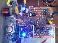
It is advisable to chose a L or T flange (heatsink) wider than 10cm to experiment later with more complex outputs.
As I said before, cascoded CFP or double cascoded, opens up even more the soundstage and other benefits, so when one realizes that the input and VAS sections are no longer the musical blottlenecks, the urge arises to experiment with different outputs.
I even shall try a simple VFET output. BTW, my (LTMD) Sony TA5650 has common source out, as you may know.
That leads me to driver's emitter resistors R39=R40=100 Ohm: in cascoded EF output configuration those emitter are better (more stable amp) not connected to output (FB) so one can replace them with a single 200R. In case one tries the more CFP complex outputs, then it is advisable to connect those R39=R40 to FB, as I understand that this will make the output more stable and even reduce its gain (?). I will explore and study further this. Maybe you can modifye the layout to allow for this variant...")
I am using R22=15 Ohm. (Zobel)
The more I study the PCB the more I admire its beauty...I haven't seen risk so far that Zobel injecting spurious signal over the input.
Is there a way to use one single heatsink for the driver and its cascode, as I've done on my experimental amps? That would also save some space. Even on VAS I used common Heatsink.
Great work.
M.
As I said before, cascoded CFP or double cascoded, opens up even more the soundstage and other benefits, so when one realizes that the input and VAS sections are no longer the musical blottlenecks, the urge arises to experiment with different outputs.
I even shall try a simple VFET output. BTW, my (LTMD) Sony TA5650 has common source out, as you may know.
That leads me to driver's emitter resistors R39=R40=100 Ohm: in cascoded EF output configuration those emitter are better (more stable amp) not connected to output (FB) so one can replace them with a single 200R. In case one tries the more CFP complex outputs, then it is advisable to connect those R39=R40 to FB, as I understand that this will make the output more stable and even reduce its gain (?). I will explore and study further this. Maybe you can modifye the layout to allow for this variant...
I am using R22=15 Ohm. (Zobel)
The more I study the PCB the more I admire its beauty...I haven't seen risk so far that Zobel injecting spurious signal over the input.
Is there a way to use one single heatsink for the driver and its cascode, as I've done on my experimental amps? That would also save some space. Even on VAS I used common Heatsink.
Great work.
M.
Last edited:
This bootstrap amp is good from +/-30V (up to 800mV input) to +/-50supplies, accepting up to 1.5V signal.
Talking about this, the BD139 will be challenged as VAS cascode at +/-50, and even at +/-44V supplies, where it would see apparently near 80V in the first case and near 70V in the second, at clipping. For that use, I'd prefer 2SC4793 which can handle much more. But I'm no expert so I will pray for any advice about which devices would be ideal here.
Note that both BJTs commented have inverse pinouts...
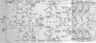
My personal "copper up" PCB is very close (9-10cm *11cm; without power transistors) to yours.
Talking about this, the BD139 will be challenged as VAS cascode at +/-50, and even at +/-44V supplies, where it would see apparently near 80V in the first case and near 70V in the second, at clipping. For that use, I'd prefer 2SC4793 which can handle much more. But I'm no expert so I will pray for any advice about which devices would be ideal here.
Note that both BJTs commented have inverse pinouts...
My personal "copper up" PCB is very close (9-10cm *11cm; without power transistors) to yours.
Attachments
I appologize because my use of BJTs with existing models creates confusion in certain positions...sorry.
Even with 50V supplies, at 23mA current, T16=VAS transistor, with a Vce under 4V, tolerates +/-24mW. So even small, low voltage units should be OK, unless malfunction, right? Even if cascoded, it would be better if its capacitance is low.
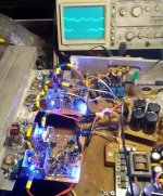
I paste with epoxi this little things, to heatsink sometimes.
On another note, while the bootstrapped version is the easiest to build, the CCS-loaded VAS version is the easiest to convert back to a bootstrapped version in case one wishes to. Converting the present one to a CCS loaded would imply creating a daughterboard and connecting it...
Cheers,
M.
PS: today I probably have a few hours to complete second channel.
I haven't checked if BC546 as VAS (T16) would tolerate power dissipation. Anyway as it only sees around 5V, maybe another, more ideal part could be found
Even with 50V supplies, at 23mA current, T16=VAS transistor, with a Vce under 4V, tolerates +/-24mW. So even small, low voltage units should be OK, unless malfunction, right? Even if cascoded, it would be better if its capacitance is low.
I paste with epoxi this little things, to heatsink sometimes.
On another note, while the bootstrapped version is the easiest to build, the CCS-loaded VAS version is the easiest to convert back to a bootstrapped version in case one wishes to. Converting the present one to a CCS loaded would imply creating a daughterboard and connecting it...
Cheers,
M.
PS: today I probably have a few hours to complete second channel.
Hello maxlorenz,
before I post an update I have to discuss the following items:
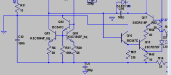
Cascode driver
The cascode transistors T21/22 (BD139/140) for the drivers
have only a low power dissipation (100mW) so there is no need
to put them on a heatsink unless you want to keep them at the same temperature as the driver transistors. I doubt that the layout wil become easier.
ECap reverse voltage
The isolation of both plates exists of a very thin oxyde layer which disolves
under a permanent reverse voltage (>0.5V). If the reverse voltage is caused by an AC voltage no clear statement could be found. It depends on the amount
of the voltage (we have up to 25V) and the current flow. A long term malfunction or change of parameters can not be excluded.
A bipolar ECap (big seize) or a series connection of 2 ECaps 220u/35V (both minus poles connected) could be an alternative.
Bootstrapping
What is the advantage of the bootstrapped variant compared to a VAS-CCS.
What is your favorite VAS-CCS to be implemented.
Trim Pot parallel to resistors 1k/2W
Is it possible to use a pluggable parallel resistor (0.5W)
to save some board space esp. in this area
transistors 2SC4793/2SA1837
The parts are discontinued and not easy to get for me.
before I post an update I have to discuss the following items:
Cascode driver
The cascode transistors T21/22 (BD139/140) for the drivers
have only a low power dissipation (100mW) so there is no need
to put them on a heatsink unless you want to keep them at the same temperature as the driver transistors. I doubt that the layout wil become easier.
ECap reverse voltage
The isolation of both plates exists of a very thin oxyde layer which disolves
under a permanent reverse voltage (>0.5V). If the reverse voltage is caused by an AC voltage no clear statement could be found. It depends on the amount
of the voltage (we have up to 25V) and the current flow. A long term malfunction or change of parameters can not be excluded.
A bipolar ECap (big seize) or a series connection of 2 ECaps 220u/35V (both minus poles connected) could be an alternative.
Bootstrapping
What is the advantage of the bootstrapped variant compared to a VAS-CCS.
What is your favorite VAS-CCS to be implemented.
Trim Pot parallel to resistors 1k/2W
Is it possible to use a pluggable parallel resistor (0.5W)
to save some board space esp. in this area
transistors 2SC4793/2SA1837
The parts are discontinued and not easy to get for me.
Hello maxlorenz,
before I post an update I have to discuss the following items:
Cascode driver
The cascode transistors T21/22 (BD139/140) for the drivers
have only a low power dissipation (100mW) so there is no need
to put them on a heatsink unless you want to keep them at the same temperature as the driver transistors. I doubt that the layout wil become easier.
Hi JOSI1, sorry for the late reply.. You are right. There is no point in heating them on the drivers heat-sink (HS). I tend to exaggerate. Anyway, if we find they heat, we can add a little HS afterwards.
ECap reverse voltage
The isolation of both plates exists of a very thin oxyde layer which disolves
under a permanent reverse voltage (>0.5V). If the reverse voltage is caused by an AC voltage no clear statement could be found. It depends on the amount
of the voltage (we have up to 25V) and the current flow. A long term malfunction or change of parameters can not be excluded.
A bipolar ECap (big seize) or a series connection of 2 ECaps 220u/35V (both minus poles connected) could be an alternative..
Well, I have two bootstrap amps and they seem OK. The Ecap will see +22-25V on the (+) lead and milli Volts on the negative, at DC. AC does not seem to make any harm, maybe due to the fact that it is not compared to ground, meaning the Ecap only sees the difference between poles. Sorry, I can't provide a better explanation now. I will try to investigate. Anyway, lets see what the experts say:
60-80W Power Amplifier
Here, Elliot doesn't even mention possible issues with its Ecap, C5. Honestly, I would only use back to back Ecaps in case I didn't have 100V units, but feel free to make the composite: I recommend 220/50V. I have seen some amps using 47uF here, so even a pair of 100uF/50V should do...
Bootstrapping
What is the advantage of the bootstrapped variant compared to a VAS-CCS.
What is your favorite VAS-CCS to be implemented.
I still don't get the whole picture about the bootstrap function (very esoteric), but what I like is the resistor loading: no "slew". Even if the cascoded CCS may be "faster" than the plain CCS, there is the problem of HF modulation, or something like that, as it is called. Apart cost, space and added complexity (failure probability) of the CCS...
Another point that I cannot answer today is what effect has the bootstrap capacitor on Thermal Memory...
I should not mention this but I've read some find bootstrap to be "musical". I can be accused of bias...
I did not had the time to complete my second channel but tomorrow I believe I can start listening tests. So at the moment I cannot say which one sounds better.
Are you asking about the CCS part of the VAS? At the moment I can only recommend the cascoded common-emitter-cascoded CCS combination, for its "symmetry" and because it proved stable. I wish we could get the cascoded emitter-follower VAS stable as it has lower THD.
Trim Pot parallel to resistors 1k/2W
Is it possible to use a pluggable parallel resistor (0.5W)
to save some board space esp. in this area
I solder extra R above the existing R: not pretty but it works and saves space. Once the exact R is defined, the potentiometer could be substituted by an appropriate R.
transistors 2SC4793/2SA1837
The parts are discontinued and not easy to get for me.
Oh! I didn't know...I bought a bunch of them on eBay. They have plastic body so it is easy to attach to the HS.
Anyway, Elliot recommends MJE15035/34, which can handle 350V!. I've used also MJE15028/31, Their fT is "low" but being cascoded I imagine the behavior is better. I will check if I can get (and use) the model...
I think any decent driver, with highish voltage handling capability will do here. I believe there are many "which driver is best" threads around here, or some mate could advice us.
Have a nice musical weekend.
M.
Last edited:
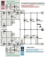
I always forget to post my recommended PS for the Amnesis. I tried to edit what I am using for my present (bootstrapped VAS) amp.
I will try to simulate it.
Any high power/voltage Schottky diodes would do. Capacitance can be increased at will.
Credit to -ECdesigns-, the inventor. The original is intended for low power circuits and includes a capacitance multiplier, here omited.
The CCS loaded VAS version is being powered for now with a SMPS with extra 20.000uF per side. It will finally have a 44V charge-transfer supply.
Attachments
Hi Max,
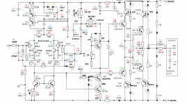
I've been reading this with interest, but I'm a little confiused by the way your "Cascode" drivers and Output devices are wired.
My understanding is that the role of Cascode is to keep the voltage across the preceeding device constant so that devicedoesn't experience the early effect.
As wired and confirmed by your simulation, Q9', Q10', Q11' and Q12' just drop the supply voltage by about 3 volts. So the serise connected devices Q9, Q10, Q11, and Q12 still experince the full voltage swing of the output.
So I suggest it's more like a regulator, but as it's referenced to the raw supply it will pass supply ripple directly to the outputs.
So I'm not sure what the idea is here?
Within the same circuit the Vas device Q7 is cascoded by Q7', because Q7' keeps the voltage across Q7 reasonably constant and hence reduces the early effect. Have you tried wiring the drivers and output devices like this?
Attachments
Dear Symon,
Thank you very much for your questions and interest. "The Mind is fed through questions, not through answers", as Einstein is supposed to have said...
I am worried too by the cascode question. Please read the following statements:
1) This is still an experimental amp. The goal of the amp is not low THD, is not high power, but is high transparency, natural dynamics and natural instrumental textures and timbres...
2) I am not an EE so I cannot answer all technical question and in fact I probably know less than half the things that I do...we learn while we experiment and create, hopefully...
3) We can divide the experiment in two: first half, the proposition of Hephaîstos and Peufeu about Low Thermal Memory Distortion (LTMD) as input and VAS modifications; seconf half, driver and output section sections best suited to exploit the full potential of the former. Since I played with cascodes and VFET I believe normal approach (EF; BJT; Mosfet) are unsuitable to critical listening...at least the kind of music that I like...
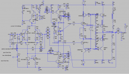
See that the LTMD mods are respected: I only added: Hagerman Vbe; Hawksford cascode; bootstrapped VAS.
4) In your own board or in JOSI1', you can wire the second half as classic EF if you like, to get the feeling of LTMD. Then, if you are inclined to do so, you can wire the cascodes and experiment with different values of Vbias and evaluate probable differences in sound...
5) I recogn I experimented a bit with the cascodying of the output but I would lie if I say that I found any change in sound when I cascoded the drivers: at that time I was more interested in getting the amp stable than anything.
6) The cascodying of the outputs, which I thought previously could only be possible in common emitter configuration, was encouraged amongst others, by Mr. Pass' classic article, which I will attach. Low Voltage bias was done with 10k potentiometer. An increase in transparency and dynamics was perceived in every amp modded. Once It was obvious that early clipping was obtained, an increase in Vbias was effected by means of the said potentiometer, without noticing any ill effects on sound quality...
7) Hephaîstos published a schematics of an "internally cascoded CFP" with a 3 diode string as Vbias (2.1V) that does not clip early. I wrongly asumed that it also could serve my simpler cascoded EF. Proper simulation and tests with ballast resistor load confirmed early clipping, so now I returned to my high Vbias, BUT, your question made re-think. I discovered that the constant V source's current biasing the cascodes is one of the limiting factors for the output swing, or at least that is what the simulations show. I attach an experimental amp with 8 diode string biasing the output BJTs and the current must be 300mA on the positive side and 200mA on the negative side to achieve +/-35V swing. You know I am a novice with LTspice so I probably did something wrong...I'll continue moddying until I feel confortable.
8) I am totally cool with a low power amplifier because I have sensitive speakers but I understand that public preference is for decent power so I am willing to improve my amp to appeal more crowd.
9) I am the only person that has listened to the amp. I would be comforted if other ears do the experiments to have a second opinion. Who knows, perhaps most people don't find that EF output is that wrong...or perhaps we feel the urge to create a VFET output. Note that I have a single ended class A VFET amp with LTMD input section that sounds great. In fact, I just received some Tokin hokey pucks to make another monster.
Thanks again and have a nice musical weekend.
M.
Thank you very much for your questions and interest. "The Mind is fed through questions, not through answers", as Einstein is supposed to have said...
I am worried too by the cascode question. Please read the following statements:
1) This is still an experimental amp. The goal of the amp is not low THD, is not high power, but is high transparency, natural dynamics and natural instrumental textures and timbres...
2) I am not an EE so I cannot answer all technical question and in fact I probably know less than half the things that I do...we learn while we experiment and create, hopefully...
3) We can divide the experiment in two: first half, the proposition of Hephaîstos and Peufeu about Low Thermal Memory Distortion (LTMD) as input and VAS modifications; seconf half, driver and output section sections best suited to exploit the full potential of the former. Since I played with cascodes and VFET I believe normal approach (EF; BJT; Mosfet) are unsuitable to critical listening...at least the kind of music that I like...
See that the LTMD mods are respected: I only added: Hagerman Vbe; Hawksford cascode; bootstrapped VAS.
4) In your own board or in JOSI1', you can wire the second half as classic EF if you like, to get the feeling of LTMD. Then, if you are inclined to do so, you can wire the cascodes and experiment with different values of Vbias and evaluate probable differences in sound...
5) I recogn I experimented a bit with the cascodying of the output but I would lie if I say that I found any change in sound when I cascoded the drivers: at that time I was more interested in getting the amp stable than anything.
6) The cascodying of the outputs, which I thought previously could only be possible in common emitter configuration, was encouraged amongst others, by Mr. Pass' classic article, which I will attach. Low Voltage bias was done with 10k potentiometer. An increase in transparency and dynamics was perceived in every amp modded. Once It was obvious that early clipping was obtained, an increase in Vbias was effected by means of the said potentiometer, without noticing any ill effects on sound quality...
7) Hephaîstos published a schematics of an "internally cascoded CFP" with a 3 diode string as Vbias (2.1V) that does not clip early. I wrongly asumed that it also could serve my simpler cascoded EF. Proper simulation and tests with ballast resistor load confirmed early clipping, so now I returned to my high Vbias, BUT, your question made re-think. I discovered that the constant V source's current biasing the cascodes is one of the limiting factors for the output swing, or at least that is what the simulations show. I attach an experimental amp with 8 diode string biasing the output BJTs and the current must be 300mA on the positive side and 200mA on the negative side to achieve +/-35V swing. You know I am a novice with LTspice so I probably did something wrong...I'll continue moddying until I feel confortable.
8) I am totally cool with a low power amplifier because I have sensitive speakers but I understand that public preference is for decent power so I am willing to improve my amp to appeal more crowd.
9) I am the only person that has listened to the amp. I would be comforted if other ears do the experiments to have a second opinion. Who knows, perhaps most people don't find that EF output is that wrong...or perhaps we feel the urge to create a VFET output. Note that I have a single ended class A VFET amp with LTMD input section that sounds great. In fact, I just received some Tokin hokey pucks to make another monster.
Thanks again and have a nice musical weekend.
M.
Attachments
Last edited:
My understanding is that the role of Cascode is to keep the voltage across the preceeding device constant so that device doesn't experience the early effect.
This is a kind of teleological thinking as: cascode to reduce Early effect, to reduce Miller effect, to reduce power stress to the device...etc. Not being an expert EE, I cascode because it sounds better this way.
Of course, optimal implementation should prove to lead to optimal sound, or at least I hope so. Even then, I would not be sure exactly what is the main reason why it sounds better...I will, as soon as my order for D44H11 arrives (yes I ran out of them), cascode the common-source output of my LTMD Sony TA-5650. In fact, I could well adapt the Amnesis to a cascoded common-source VFET output IF my experiments with the Sony go as expected.
As I commented before, once I get the new amps working OK I'll probably take the plunge and replace the cascodying element with complementary VFETs: that should solve the Vbias dilemma. I wish I had some output waveforms for the VFET amps...wait, I seem to remember now...
Today, I hope to finish channel n°2 and make further simulations for the biasing problem.
Cheers,
M.
Last edited:
OK. Second channel ready. SMPS, CCS loaded VAS, hawksford cascode, low bias.
This still has the cascoded output with a 3 diode string, for a whooping 1,6V Vce for the main output transistors!
I had not the time to simulate or experiment, but even at this low power, this amp produces music so sweet that it is an imperative to solve this cascode issue...if I can get at least 25V swing I'll be a happy man.
Until wednesday...
M.
Attachments
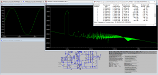
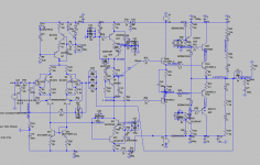
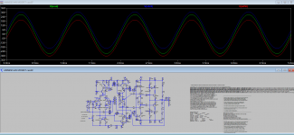
In the following experiment, an independent, floating V source of 7V5 is attached to both bias nodes for the output cascodes, and then a 5 diode string to FB node.
A clean 25V swing is achieved, with 900mV signal, with decent THD, and only 3.4Vce for the output transistors.
With a 6 diode string, a 9V source would do, like a battery. The simulations say only 39mA of consumption.
Perhaps this is good enough...
Cheers,
M.
A clean 25V swing is achieved, with 900mV signal, with decent THD, and only 3.4Vce for the output transistors.
With a 6 diode string, a 9V source would do, like a battery. The simulations say only 39mA of consumption.
Perhaps this is good enough...
Cheers,
M.
Attachments
Last edited:
The floating V source trick also serves to cascode the drivers...though to some the difference may look as marginal: look at the plots with simple drivers (no cascode)...maybe only listening test will tell the difference, IF any...
Attachments
Last edited:
Hi Max,
a suggestion to improve distortion fiqures is to add a helper transistor to the input stage current mirror, and an emitter follower to buffer the VAS stage and reduce loading on the input. See attached.
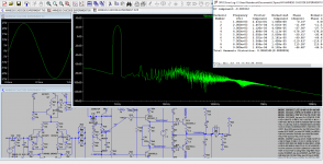
After playing with the simulation the distortion figures dropped from 0.006 to 0.004, but at the end of the day it's what is sounds like that matters.
A further though on output cascodes, is that generally power devices like 2SC5200 and 2SA1943 are high voltage devices, and have high Cob values when operated with low VCE calues as you have in this Cascode arrangement. As such Cascoding the outputs might make the Cob more consistant, but as it's now always a high Cob value perhaps not always better?
As you say listening is the actual proof.
Regards
Symon
a suggestion to improve distortion fiqures is to add a helper transistor to the input stage current mirror, and an emitter follower to buffer the VAS stage and reduce loading on the input. See attached.
After playing with the simulation the distortion figures dropped from 0.006 to 0.004, but at the end of the day it's what is sounds like that matters.
A further though on output cascodes, is that generally power devices like 2SC5200 and 2SA1943 are high voltage devices, and have high Cob values when operated with low VCE calues as you have in this Cascode arrangement. As such Cascoding the outputs might make the Cob more consistant, but as it's now always a high Cob value perhaps not always better?
As you say listening is the actual proof.
Regards
Symon
Attachments

Hi Symon,
I'll reply to you later as I am in a hurry.
I received some Zeners...active and external Vsource solutions attached.
Yeah, the choice of 3055 as cascode was bad for simulations: asymetric clipping...
I'll reply to you later as I am in a hurry.
I received some Zeners...active and external Vsource solutions attached.
Yeah, the choice of 3055 as cascode was bad for simulations: asymetric clipping...
Attachments
Hi Max,
a suggestion to improve distortion fiqures is to add a helper transistor to the input stage current mirror, and an emitter follower to buffer the VAS stage and reduce loading on the input. See attached.
After playing with the simulation the distortion figures dropped from 0.006 to 0.004, but at the end of the day it's what is sounds like that matters.
Interesting trick. Can you elaborate on the function of the helper T?
I've simulated a "buffer" for that output which is in fact a cascoded-cascoded-CFP for the input. I have not tried it yet.
When I use the EF VAS, I got sometimes the dreaded HF oscillation at (negative) peaks, so, for now I will concentrate on the output cascode and after I will re-visit this topic.
A further though on output cascodes, is that generally power devices like 2SC5200 and 2SA1943 are high voltage devices, and have high Cob values when operated with low VCE calues as you have in this Cascode arrangement. As such Cascoding the outputs might make the Cob more consistant, but as it's now always a high Cob value perhaps not always better?
As you say listening is the actual proof.
Regards
Symon
Indeed, now that output Vce is low, we can use smaller transistors, with lower Cob, an parallel them if needed. Like Sony, that uses 2SC1173/2SA473 old 30V/3A devices paralleled as outputs for its TA-N7 amp (VFETs as cascode elements) and we can use bigger BJTs in common-base, which eliminates Cob as a problem.
Thanks for your support,
M.
Attachments
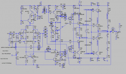
Hi Max,
the helper transistor as shown in the attached schematic is Q12, and improves teh symetry of the current mirror, this is one of several standard improved current mirror designs. This was something I took from Bob Cordells book, although this current mirror circuit is well documented in many places.
I was a little confused by your comment about the instability you observered buffering the VAS, but it seems like you used it to buffer the output of the VAS?
I was proposing input buffer which is Q16 in the attached schematic. This reduces loading on Input stage and this helps keep he differential pair in balance.
I've seen this technique of using an emmitter follower before the VAS this way in several books by Bob Cordell, Douglas Self, and Randy Sloane. If it becomes a problem increase the feedback resisters to reduce the voltage gain.
But the important thing is try it and see what it sounds like.
I continue to follwo your developments with interest.
Symon
Attachments
Hi Max,
the helper transistor as shown in the attached schematic is Q12, and improves teh symetry of the current mirror, this is one of several standard improved current mirror designs. This was something I took from Bob Cordells book, although this current mirror circuit is well documented in many places.
OK. About that, I tested cascoded-current mirrors, just to remain in the same philosophy
but first attempts were difficult...I shall evaluate this afterwards.I was a little confused by your comment about the instability you observered buffering the VAS, but it seems like you used it to buffer the output of the VAS?
I was proposing input buffer which is Q16 in the attached schematic. This reduces loading on Input stage and this helps keep he differential pair in balance.
I've seen this technique of using an emmitter follower before the VAS this way in several books by Bob Cordell, Douglas Self, and Randy Sloane. If it becomes a problem increase the feedback resisters to reduce the voltage gain.
Symon
Yes, the buffered VAS or emitter-follower VAS is great but in this particular amp (and in another ongoing thread about Blameless type amp) it has shown tendency to (delayed) oscillation in the power peaks. Increasing emitter (or collector) R apparently does not control this. As Hawksford cascode VAS works finelly and sounds good (yes, yesterday I was listening to the new CCS loaded VAS amp again
) I will postergate further study of this topic...As I mentioned before, one of the problems with the Amnesis is that, in order to make and test the putative upgrades one has to power off the amp first! That is the difficult part...for example, yesterday I had a couple of hours to invest in the "floating Vsource" mod, but I was so moved listening to some music on youtube that I could not complete it. Not to mention that yesterday we had -2 to 9C° outside, erhh in my workshop...BTW, I only got 6V2 and 7V5 zeners...I suspect lower ones, like 5V1 or lower, could be better for this application.
Good news.
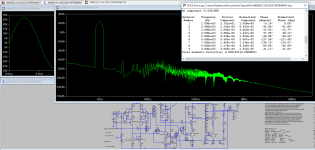
Apparently, the easiest way (apart from VFETs) to get a cascoded output for the amp is using MOSFETs as cascode, common-gate elements. This is probably due to the low current need for the gates.
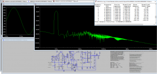
I attach simulations for a MOSFET cascode with 6V2 zeners plus resistor based Vsource. I makes +/-35V outputs with 1.3Vsignal, unclipped. One volt THD test are decent but no great. I used some MOSFET models available. Suggestions are welcome...I think I have still some lateral MOSFET around...
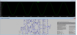
I forgot: green is output; blue and red are collectors "outputs", showing no clipping.
I hope you like it...I like it.
Apparently, the easiest way (apart from VFETs) to get a cascoded output for the amp is using MOSFETs as cascode, common-gate elements. This is probably due to the low current need for the gates.
I attach simulations for a MOSFET cascode with 6V2 zeners plus resistor based Vsource. I makes +/-35V outputs with 1.3Vsignal, unclipped. One volt THD test are decent but no great. I used some MOSFET models available. Suggestions are welcome...I think I have still some lateral MOSFET around...
I forgot: green is output; blue and red are collectors "outputs", showing no clipping.
I hope you like it...I like it.
Attachments
Last edited:
- Home
- Amplifiers
- Solid State
- The AMNESIS amp: a good amplifier, like a gentleman, has no memory.