Request for Help to Understand the Kenwood KA-4000 amplifier High Pass Section
Good evening,
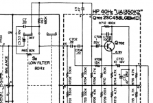
I have been pondering the 40Hz HP section (see pic) of this 1969 Kenwood amp for a good while and cannot make sense of how it works. (I am no EE, and still at the beginning of audio learning). Therefore I would like to ask for some help in understanding the schematic.
Is the HP always in or is it switchable? The switch depicted in the schematics is for a 80Hz HP, however. In any case I can't figure how the RC network works. Which Cs and which Rs from the schematics are implied?
To me it seems that the HP section of the KA-4000 is always in the circuit. A very similar HP section is in the KA-6000, albeit with an additional switchable 40Hz filter. The KA-6004 does have two seperate modules for low pass and high pass.
I will be grateful for some clarification! Thanks in advance.
Good evening,
I have been pondering the 40Hz HP section (see pic) of this 1969 Kenwood amp for a good while and cannot make sense of how it works. (I am no EE, and still at the beginning of audio learning). Therefore I would like to ask for some help in understanding the schematic.
Is the HP always in or is it switchable? The switch depicted in the schematics is for a 80Hz HP, however. In any case I can't figure how the RC network works. Which Cs and which Rs from the schematics are implied?
To me it seems that the HP section of the KA-4000 is always in the circuit. A very similar HP section is in the KA-6000, albeit with an additional switchable 40Hz filter. The KA-6004 does have two seperate modules for low pass and high pass.
I will be grateful for some clarification! Thanks in advance.
Attachments
Last edited: