For offset removal purposes a resistor can be inserted in series with source terminal of the JFET of the pair with higher transconductance. The value of the resistor can be estimated so that the typical drain current causes a voltage drop in the resistor similar to the offset (assuming the circuit has unity gain at DC).
For example, if the gate of TR105 is 100mV over the gate of TR103, and the drop across (R165,R167)=6.8k is X volts, a resistor R=.1/(X/6800) could be inserted in series with the source of TR103.
EDIT: Remember that, in pair of mismatched JFETs, one will have higher transconductance, so the resistor does the matching.
Last edited:
They are both 1.18kOhms, and they have a 680mV drop on them.
good.
.......and R199 (at TR111): volt and ohm , and on the opposite side at TR112.
R199 is 16.2Ohms, with 41mV drop. R200 is 15.9Ohms with 49mV drop.
Last edited:
For offset removal purposes a resistor can be inserted in series with source terminal of the JFET of the pair with higher transconductance. The value of the resistor can be estimated so that the typical drain current causes a voltage drop in the resistor similar to the offset (assuming the circuit has unity gain at DC).
For example, if the gate of TR105 is 100mV over the gate of TR103, and the drop across (R165,R167)=6.8k is X volts, a resistor R=.1/(X/6800) could be inserted in series with the source of TR103.
EDIT: Remember that, in pair of mismatched JFETs, one will have higher transconductance, so the resistor does the matching.
I have inserted the pots into the circuit, and made the adjustments. The offset less than 5mV now. Thank you!
Hello
I am also repairing a Yamaha A 520 today .
It has been tampered and both channels don’t work.
I have replaced TR123 – TR121 – TR119 – TR117 and R 289 all on the same channel.
On the other channel , although it was tampered , it's all right.
But from both channels, exits a positive DC voltage (trying with VARIAC) close to the power supply value.
If I remove the collectors of TR 113 and TR 112 and I install a resistive divider to simulate the voltage on the collector (1,2V),
I have no more the loss voltage, but both amplifiers still don’t work.
I repeat, both channels have the same loss voltage and the supply voltages on the FET are the same.
Same ideas?
Thanks
Please verify that you have a good ground connection at C143/C144(-).
With the volume turned down all the way (Subsonic: OFF!), you should also be measuring a low resistance to ground at R159/160.
Also verify that all of R179-190 are good, along with pot VR104. Same for R207-210, R215-218 and R219-222.
(BTW, there is no R289, did you mean R189?)
Next step - with power on, measure voltages across:
a) R199/200
b) R177/178
c) R171/172
d) R165 + R167 / R166 + R168
e) R163/164
Have you checked whether you can set output stage idle current to spec?
With power off again:
Check resistors (a) to (e) for opens (values much higher than specified)
Check TR107/109/111 (+108/110/112) using diode test (watch out for p-n drop, any obvious shorts, possible opens). Same for TR125/126, which would trigger overcurrent protection if shorted C-E and may have been damaged.
Check TR103/105 (+ 104/106) for any obvious shorts.
Test all diodes for obvious shorts and possible opens (D101-104, D119-126).
If you want to rule out the current sources TR113 + TR114 (I hope you meant those two, TR112 is a VAS transistor!), replace by an approx. 18 kOhm resistor to V+. I don't know what you were doing with voltage dividers there.
If you want to test the output stage by itself, remove collectors of TR111/112 and connect output stage input to ground. That'll give you a ca. +1.2 V output offset but should at least allow you to verify operating currents. I would only go to the trouble of trying to get 0 V at the output if you want to see whether the amp will come out of protection, but IMHO this can wait until the amplifiers are basically operational again.
This should do for now, tell us what you find.
Last edited:
Sgrossklass, thank you very much for the very detailed help.
R289: I meant this (resistor in series to D125, Zener 6,1V , strangely I found it good)
R289 and R290 unlike the scheme, on the amplifier they are 10 ohm
TR112 : yes, I was wrong. I meant 113-114
I created a resistive divider test, to have on the collector of TR 113, 1,2V (like schematic)
I will make the measurements that you have advised me.
In particular I will check the ground voltages.
I will ceck if there are problems on the PCB
(because reasonably it seams a problem of this type)
I had already checked all the components you indicated to me.
good.[QUOTE
They are both 1.18kOhms, and they have a 680mV drop on them.
.......and R199 (at TR111): volt and ohm , and on the opposite side at TR112.[/QUOTE]
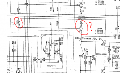
Hi There, this was an oldish posting, but is close to where I have an issue with my AMP. The problem is really poor quality schematics, but also looking for some advice.
R178 is overheating and smoking
I suspect TR112 may be shorted? Is that the most likely issue? Does anyone have the Part Number for TR112?
Cheers!
Attachments
- Status
- This old topic is closed. If you want to reopen this topic, contact a moderator using the "Report Post" button.
- Home
- Amplifiers
- Solid State
- Yamaha A-520 clipping and distortion