Hi Brad,
Here's a summary with the different options for the Alpha.
With added 0.11 sensor options.
Regards,
Danny
Here's a summary with the different options for the Alpha.
With added 0.11 sensor options.
Regards,
Danny
How would you guys like a 25w Alpha amp? Hugh’s latest studies show that using two trafos, one for 24vdc rail and one for -27vdc, and having each trafo feed two amps but opposite rails lowers the negative clip point to essentially make the Alpha a 25w amp. No extra cost if you had planned on getting two trafos to start.
So even if you have one all running now, simple addition of another 22vac trafo (for -27vdc after sag) will boost power and give more headroom.
So even if you have one all running now, simple addition of another 22vac trafo (for -27vdc after sag) will boost power and give more headroom.
Well I could check the behavior with lab supply. I will put on the overcurrent, but you got to wait, for my al2o3 insulator to arrive.
I put the irfp on copper water cooler!
I I got work too, & putting a Schmitt trigger nand & comparator with Relay for loudspeaker insulation on power on/off & dc detection.
I put the irfp on copper water cooler!
I I got work too, & putting a Schmitt trigger nand & comparator with Relay for loudspeaker insulation on power on/off & dc detection.
Last edited:
How would you guys like a 25w Alpha amp? Hugh’s latest studies show that using two trafos, one for 24vdc rail and one for -27vdc, and having each trafo feed two amps but opposite rails lowers the negative clip point to essentially make the Alpha a 25w amp. No extra cost if you had planned on getting two trafos to start.
So even if you have one all running now, simple addition of another 22vac trafo (for -27vdc after sag) will boost power and give more headroom.
What would the power supply look like? Would you need two power supplies?
Brad,
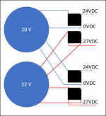
No change to existing supply. Just one trafo with 20Vac secondaries, one winding to positive rail one channel and the other winding to the positive rail other channel. The second trafo would have 22Vac secondaries, with one winding to negative rail of channel ONE and the other winding to negative rail of channel TWO.
No changes. No additional parts or cost. Just two different trafos. You go up from 19W to 25W, and increase of 31% for peanuts.
Hugh
I took C103 off yesterday, connected + to pcb and jumped - to otherside of ground lift. Now theres loud buzz that stops when I touch the RCA-connector or even rca wire. Tried two cables and same effect 
Edit. If I tie both RCA grounds together, hum goes almost away, but it's not as quiet anymore as it used to be. Only change I made was C103 negative leg to otherside of 10r ground lift.
Worked whole morning with this, and going to remove C103 - mod right now. It seems to cause strange grounding troubles that I can't solve.
More cheap than Mundorf MLGO. A big bank capacitors with the GPD maybe it is a good idea with ALPHA20.
United Chemi-Con GPD miniature electrolytics measures at 100 kHz
https://www.mouser.com/datasheet/2/420/UCC_GPDDatasheet-1210831.pdf
7500uF 35V EGPD350ELL752MM40H
https://www.mouser.es/ProductDetail/United-Chemi-Con/EGPD350ELL752MM40H?qs=IYueExuAvkp0C0aPkPvYcQ%3d%3d 3,74 €
The very expensive Mundorf MLGO measures at 100 Hz
http://www.mundorf.com/english 1.1/Broschuere Einzelseiten/MLGO.pdf
United Chemi-Con GPD miniature electrolytics measures at 100 kHz
https://www.mouser.com/datasheet/2/420/UCC_GPDDatasheet-1210831.pdf
An externally hosted image should be here but it was not working when we last tested it.
7500uF 35V EGPD350ELL752MM40H
https://www.mouser.es/ProductDetail/United-Chemi-Con/EGPD350ELL752MM40H?qs=IYueExuAvkp0C0aPkPvYcQ%3d%3d 3,74 €
The very expensive Mundorf MLGO measures at 100 Hz
http://www.mundorf.com/english 1.1/Broschuere Einzelseiten/MLGO.pdf
An externally hosted image should be here but it was not working when we last tested it.
Last edited:
Worked whole morning with this, and going to remove C103 - mod right now. It seems to cause strange grounding troubles that I can't solve.
So I am not sure what you did here. C103 needs to be referenced to the non-lifted power ground. If the entire PCB is already lifted with a 10R (I assume this is what is being done as the Alpha 20 has no built in 10R lift) then probably ok to leave it lifted. It’s in the case of the Alpha BB where some parts were lifted and parts were not, then better referenced to power ground. If you can mark up the schematic with what is actually implemented, it would help us to debug with you.
So I am not sure what you did here. C103 needs to be referenced to the non-lifted power ground. If the entire PCB is already lifted with a 10R (I assume this is what is being done as the Alpha 20 has no built in 10R lift) then probably ok to leave it lifted. It’s in the case of the Alpha BB where some parts were lifted and parts were not, then better referenced to power ground. If you can mark up the schematic with what is actually implemented, it would help us to debug with you.
That's what I did. But I think I solved the problem finally. Reason was one wire that seemed to pick up RF signals or something like that, even it was not close to anything. And that must have turned RCA-cable to antenna (?) because when I placed my hand over signal cable, humm went away?
Jun,
Try another cap - try 470uF
HD
Thanks Hugh I'll try that later. Now I'm full with soldering!
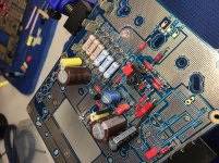
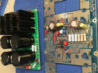
Making some progress on the BB and psu
Vunce,
Good to see the build progressing, and your handiwork looks neat!
Brad,
No change to existing supply. Just one trafo with 20Vac secondaries, one winding to positive rail one channel and the other winding to the positive rail other channel. The second trafo would have 22Vac secondaries, with one winding to negative rail of channel ONE and the other winding to negative rail of channel TWO.
No changes. No additional parts or cost. Just two different trafos. You go up from 19W to 25W, and increase of 31% for peanuts.
Hugh
Hugh,
Is this what you means?
Brad
Attachments
- Home
- Amplifiers
- Solid State
- Aksa Lender P-MOS Hybrid Aleph (ALPHA) Amplifier