if its the case can I use a higher wattage and low resistor on the CRC psu board to achieve the required voltage.
Thanks
on the contrary, higher the value of resistor= more voltage drop, courtesy Ohms law
") .
.Can I use a 0-22v 6.8A x2 (dual secondary) toroidal for the Alpha 20W board? Is the voltage more and if its the case can I use a higher wattage and low resistor on the CRC psu board to achieve the required voltage. I have this in spare which I can use and if not this I need to use my other spare 0-18v 7A x2.
Thanks
That can work as there is about a 3v-4v drop due to sag from running at high current and then maybe a 10w 2.2R resistor in CRC to take another 3v drop. You will be burning off about 5w per resistor. The ripple will be very low with kind of CRC.
Thanks for the reminder X.
In preparation for that mod, I left the one leg of the 10R resistor long and bent it into a loop under the board to make a solid anchor point for the C104 GND wire
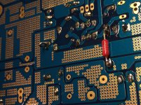
And don't forget to put insulating washers or Kapton tape on the board underneath where the nut/washer goes to mount the CPU coolers. The exposed vias are sometimes connected to the rails or the output there. CPU cooler will typically be at ground potential.
Look in photo below and see where I put the tape 92 layers) underneath the washers.
Last edited:
X,
I picked up a roll of Kapton tape and will make sure all the areas in question are insulated.
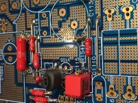
From the start, I’m leaving C111 empty and installed sockets at R154 for easy experimenting with different capacitor values. In the picture you can see the 18K resistor soldered underneath. Also visible is the small loop for the C104 GND to power GND modification (not required for the April BB version).
I picked up a roll of Kapton tape and will make sure all the areas in question are insulated.
From the start, I’m leaving C111 empty and installed sockets at R154 for easy experimenting with different capacitor values. In the picture you can see the 18K resistor soldered underneath. Also visible is the small loop for the C104 GND to power GND modification (not required for the April BB version).
Attachments
So I'm gathering the parts for my 20W build and have some questions.
I have an easily load running Blumenstein Orca speakers with separate amp for subs. The drivers are the Fostex FE83En-SOLs, so it is an easy load and they don't dip below 8oHms.
I'm following the diagram that X put notes on. In addition I'm going the use a 15K oHm in R113. I will use IXFH74N20P and IXTH90P10P MOSFETs.
Not sure if I want make the other changes to reduce the gain even more (remove C105, use 22pF C113, and increase R111 to 2.2K oHm). Vunce would like to get your feedback on this implementation not that you have had it for a little time.
I'm thinking that because my peramp has 20db gain I need to get the amp gain down as low as possible without compromising the sound.
I'm not sure about what way to go with the power supply? Do I get AnTek 400VA 18V and use the PS from the DIYA store? Is the 18V transformer enough, because I thought I read that 20V would be better? The JPS PS looks real nice and has separated supplies for each channel. Any suggestions would be appreciated.
Thanks,
Brad
I'm not sure about what way to go with the power supply? Do I get AnTek 400VA 18V and use the PS from the DIYA store? Is the 18V transformer enough, because I thought I read that 20V would be better? The JPS PS looks real nice and has separated supplies for each channel. Any suggestions would be appreciated.
Get the 20v and increase R in the CRC as needed to adjust correct voltage. The 18v sags too much.
I'm following the diagram that X put notes on. In addition I'm going the use a 15K oHm in R113. I will use IXFH74N20P and IXTH90P10P MOSFETs.
Not sure if I want make the other changes to reduce the gain even more (remove C105, use 22pF C113, and increase R111 to 2.2K oHm). Vunce would like to get your feedback on this implementation not that you have had it for a little time.
Hi Brad,
Initially, I reduced R113 to lower the gain but, after conferring with Hugh, Danny and X, the better way for this is to increase R111. So, I put back the 22K resistor at R113 and increased R111 to 2.2k. Changing R111 reduced the gain to approximately 21dB.
Removal of C105 and increasing C113 does not effect gain.
I’m using an Antek AS-4220 with diya’s universal psu and get 25vdc with both ALPHA boards connected. (1.35A bias setup .47R/.22R)
Hope this helps out a little bit.
Good luck with your build
Cheers,
Vunce
Very good approach, Vunce.
In a LTP input stage like the ALPHA you should leave the input bias resistor to ground and the series fb resistor from output to T2 base. Both are 22k, and this sets the input impedance of the amp which is generally selected during early design.
If you want to change the gain, you are best to change the shunt resistor to fb cap. This is normally 1k, or 1k5 in some. It can be increased again to 2k2. But there is a subtle change in the circuit when you do this.........
By changing the closed loop gain you are changing the LOOP gain of the amp. This is the ratio of the amp's OPEN loop gain (ie with no feedback at all) to the amp's CLOSED gain, which is set by the ratio of 22k and 1k5, that is, (22k+1.5K)/1.5k. This LOOP gain tells you how much feedback you are using, and predicts within some limits by how much you will reduce the distortion wrt the open loop gain THD. And this brings us to the compensation of the amp, the technique we use to ensure that the amp is always stable across a large frequency and output.
If LOOP gain is HIGH, like many very low THD amplifiers, compensation is critical and difficult to achieve. If the LOOP gain is LOW, like the ALPHA which is set by 20dB, only 10:1, the compensation is not too difficult. We achieve that compensation on the ALPHA with a 22pF from output at source of pmos back to the fb node, the base of T2. It's so low, and so uncritical, that minor changes to the fb network should not have any affect. But if you set the shunt fb resistor from 1k5 down to say 10k you would then have a much higher LOOP gain and you might be need to alter the compensation cap, generally by increasing it, to keep the amp stable.
An unstable fb amp simply means that the fb signal presented to the fb node, normally the base of T2, has undergone more than 180 degrees of phase shift at a high frequency, well above 1MHz in fact, so that global feedback has now been transmuted into POSITIVE feedback. Positive fb means that a small increase of input creates a small increase to the SAME input, increasing the output a second time, and then a third, and then a fourth, and up to rail as a positive clip. When the signal reverses its polarity, the output immediately swings to negative clip as well, with the amp then flip flopping rail to rail until it destroys itself. Very nasty...... and every expensive. This is the classic behaviour of control theory.
Cheers,
Hugh
Hi guys,
I am in the process of gathering parts for my Alpha BB build and have a couple questions concerning parts.
1) R119 (925R) Where is the source for these?
2) R143,R144 (47R) Mouser part# 660-RK73H2ATT047R0F is this ok?
3) C143,C144 (220pF) Mouser part # 810-C8J4C2C062A221J or 505-FKP0D002200BK55D (Wima FKP02) is this ok?
Thanks
X, Vince, Hugh,
Thanks for the feedback and input. Not sure exactly which way to go with the amp with respect to the input. I will make sure I have all the parts necessary to go with either configuration when the time comes.
I already have a DIYA PS so will use it. Ordered a 20V transformer and will make sure I have resistors to adjust to 24V.
Brad
Yikes, edit timed out.
2) R143,R144 660-RK73H2ATTD47R0F
3) 77-VJ0805A221GXJPBC or 505-FKP0D002200BKSSD
R143/144 are little 0805 SMT thick film snubber resistors. The cap that goes with them should be NP0/C0G ceramic SMT 0805. I did not have any on hand so improvised with Wima film caps. I am told better to use NP0.
- Home
- Amplifiers
- Solid State
- Aksa Lender P-MOS Hybrid Aleph (ALPHA) Amplifier