Ah, my mistake........ it could be that there is a conflict with the earthing.
If the smps have referenced output to the mains, they will fight each other if one is a positive supply and the other a negative supply. Then, they will turn off to protect high current.
If both outputs, pos and neg, on each smps, I'm lost, but if there is a reference to mains earth (which is normally to neutral) then there will a conflict and it can't be connected this way. Do you have ohmic connection from pos or neg of the smps back to mains earth?
Hugh
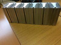
Hi Prasi, sorry I have no information about them, I removed them from an old industrial three phase rectifier cabinet that was being scrapped. I do not know the manufacturer or any part numbers.
At the moment I have fixed some metal clad resistors to the sink and supplying a voltage that equates to 90W to see temperature rise above ambient.
regards
At the moment I have fixed some metal clad resistors to the sink and supplying a voltage that equates to 90W to see temperature rise above ambient.
regards
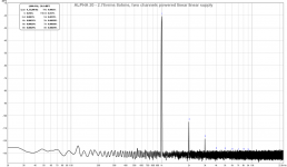
They are silent, no hum, hiss or any artifacts of any kind. Music sounds very good.
Now comes the puzzling part? When both boards are connected to the power supply, 2 seconds after the power switch is flipped both smps’s shut down.
If only one amp board is connected it works perfectly.
Any thoughts?
How close to max power output of the two bricks are you ?
I am fired up!! Mostly great news with a little bit of a puzzling situation.
Both amp boards are working and within spec for dc offset and bias voltage.
Board 1: 17.5mV offset, .604v bias
Board 2: 16.5mV offset, .603v bias
They are silent, no hum, hiss or any artifacts of any kind. Music sounds very good.
Now comes the puzzling part? When both boards are connected to the power supply, 2 seconds after the power switch is flipped both smps’s shut down.
If only one amp board is connected it works perfectly.
My power supply consists of:
(2) 24v smps->(2) dc voltage boosters->(2) cap Mx
The outputs of the cap Mx are wired in series to get +v/-v/0v before feeding the amp boards.
Any thoughts?
Vunce,
Congrats on successful first sound!

Nice work and shows that following the schematic results in a working amp.
I think your problem is that you did not adjust the current limiter on the DC step up. It’s the “other” trimpot (the one on the bottom with current flowing left to right). Adjust the pot clockwise I believe until the voltage can be maintained. This happened to me too. Those DC step up boards will get hot pulling close to 4.3amps. The other thing might be that the cap Mx doesn’t have a slow enough turn on slope under high load. I suspect it’s the current limit pot.
Cheers,
X
Edit: but you are saying it is your SMPS that is shutting down? That means that there is too much current being pulled through them or that the Allo doesn’t have a slow enough start up ramp. Is there a way to increase the tine constant of the startup? On the Juma cap Mx, it’s a 10k resistor charging a 220uF cap that is being “multiplied”. T=0.6RC gives 1.3sec and that is good enough to prevent shutdown. Look on Allo cap Mx for the cap being multiplied and resistor charging it. Easiest thing to try is to double the cap by soldering another to the bottom of the board. That will double the time constant and maybe prevent auto shutoff of SMPS.
Last edited:
The IC that controls it is covered up with white silicone used to bond the large inductor sitting on top of it. I am sure it is probably a reference design from a spec sheet somewhere. I would just have to break one of mine apart to get the numbers. I have the one with external metal heatsinks and two MOSFET or BJTs and they use TI TL494C with NCE8580 and ON B20100G - also with dual trimpots.
http://www.ti.com/lit/ds/symlink/tl494.pdf
The metal core has only a single external transistor (a D-PAK) and is boost only whereas the other is boost/buck.
http://www.ti.com/lit/ds/symlink/tl494.pdf
The metal core has only a single external transistor (a D-PAK) and is boost only whereas the other is boost/buck.
Hi X,
Martin Jones has the schematics for the standard unsurprisingly boost converter (sidely mounted external heatsinks):
150W Boost Converter Schematic | martinjonestechnology
But I´m really interested in some retro engineering schematics of the metal core one.
JP
Martin Jones has the schematics for the standard unsurprisingly boost converter (sidely mounted external heatsinks):
150W Boost Converter Schematic | martinjonestechnology
But I´m really interested in some retro engineering schematics of the metal core one.
JP
Hi X,
I removed the DC voltage boosters and the SMPS’s still shut down when both amplifier boards are connected.
I can’t find a schematic for the CapMx, but there is only two electrolytic capacitors and four poly capacitors on the board. There are SMD resistors on the underside I will have to figure it out by following all the traces.
Hi Vunce,
I looked at the traces on the Allo CM and it is totally different topology than the Juma one. So I don't even know if it has the soft start mechanism. The two big electrolytics are connected to the input jack and the output pins so both for smoothing/ripple control. Neither are fed through a high impedance resistor so I do not know which one it is looking at the traces. You have the Prasi/Juma cap Mx board, maybe try building it?
What is your 24v SMPS rated for in amps?
My SMPS’s are rated for 5 amps.
I’m starting to think for higher power, dual rail power supply requirements that the smps bricks are not an attractive option. For single rail supply (MoFo) they work very well.
I’ll probably be going the conventional linear PS with the Juma E-P board next.
Can the ALPHA20 handle up to +/-28vdc input?
Can the ALPHA20 handle up to +/-28vdc input?
Yes, I have tried it in fact. THD goes way down but heat goes way up - if your heat pipes and fans can do the job, give it a go. With 28v trafo, under load may sag to say, 26v, so dissipation is P=26vx2x1.8amps= 94W per channel (or per heatsink since you got 2). Those Dell CPU coolers are good for 120w with the proper fan.
I think I will be going with linear PSU as well for same reason. Under sustained high current use, big iron seems to work without complaining (as in auto-shutdown).
Although, you could try a 6.5amp Meanwell:
LRS-150-24 MEAN WELL | Mouser
Last edited:
Working with the case and PSU, what do you think X, is it possible to achieve ripple free PSU without extra CRC supply after Jumas capMX? I have big capacitors on MX, 22000uF. I have 4x spare 22000uF but do I even need them? Should have 4 more for two separate CRC's and thats why I would not like to go that way.
Working with the case and PSU, what do you think X, is it possible to achieve ripple free PSU without extra CRC supply after Jumas capMX? I have big capacitors on MX, 22000uF. I have 4x spare 22000uF but do I even need them? Should have 4 more for two separate CRC's and thats why I would not like to go that way.
It should be good without extra CRC if your DC-DC converter is fairly benign and your SMPS is free of broadband white noise (I have encountered those before). Often you can't hear it, but can measure it. I am just obsessive about it and want to know it's flat to the floor.
 But that's just me....
It should be good without extra CRC if your DC-DC converter is fairly benign and your SMPS is free of broadband white noise (I have encountered those before). Often you can't hear it, but can measure it. I am just obsessive about it and want to know it's flat to the floor.
Not going for SMPS route, already ordered shielded 500VA 2x20v toroid from Toroidy
I'm old fashioned guy. Is there any reason to add just after MX only 2x20000uF per rail without R or L between?If you have 4x33mF in CRC per amp channel you should be good without a cap multiplier. The idea with multiplier is to only need maybe a single 4700uF cap vs four 33mF caps. But with big electrolytics, the more you have, it’s always better.
Ok, so I don't add those extra caps atleast in this point, I wasn't sure how much capacitance I can "replace" with capMX
thanks!Mounted metal clad resistors to my heat sink and let it run dissipating 90W . After four hours it was 20C above ambient ( 23C ambient ) so I suspect it can handle a bit more. With that in mind are there advantages of say using 28V rails and using FDA38N30 and FQA36P15 instead of IRFP240 /9240. I believe Hugh suggested those output devices at the start of this thread.
I am about to begin ordering parts so if anyone has any comments regarding this I would be grateful.
Regards
I am about to begin ordering parts so if anyone has any comments regarding this I would be grateful.
Regards
Attachments
- Home
- Amplifiers
- Solid State
- Aksa Lender P-MOS Hybrid Aleph (ALPHA) Amplifier