Don´t forget, step up converter is more noise on output then input...
http://sl-div-bi-pb.web.cern.ch/sl-div-bi-pb/PrivatePBpage/CERN/CERN-Misc/emc.pdf
JP
http://sl-div-bi-pb.web.cern.ch/sl-div-bi-pb/PrivatePBpage/CERN/CERN-Misc/emc.pdf
JP
I’ve got a question about the trim pots at positions
R1270 and R125 and resistors R127 and R124. Should I install trim pots first, adjust settings and then remove and replace with fixed resistor values?
Do I even need a pot at R125 at all?
R125 just skip and leave R124 as a fixed resistor if you had to choose. R1270 allows you to adjust the depth of the Aleph CCS action. If you want to get going quickly, I think it may be enough to skip all trimpots and if testing shows that it needs adjustment. However, R1270 would be the one to have if you needed adjustment. R105, the one above the LTP (actually LNP - long neck pair) could be fixed at 1050ohms. So my recommendation is to install R125 as fixed 1050R (or use 1k plus 47R series), and put a pot at R1270 set to 1000ohms. R124 should be 100k and skip the pot R125.
Last edited:
I don't know about you guys but I used the same chassis with an Antek 500 va 18/18 (non shielded) for a few Pass amps,Aleph J,F6,M2 and now F7ish and have not had any hum or noise like others have reported.My trafo is at the rear of the amp and the rectifiers (cheap fwbs) and diy audio ps board is to the front.I've seen many the other way around.I don't know if that has anything to do with it or I have just been lucky.Also the trafo is held down REALLY tight.I guess they don't offer shielded in the 500va and 600va series?
I don't know about you guys but I used the same chassis with an Antek 500 va 18/18 (non shielded) for a few Pass amps,Aleph J,F6,M2 and now F7ish and have not had any hum or noise like others have reported.My trafo is at the rear of the amp and the rectifiers (cheap fwbs) and diy audio ps board is to the front.I've seen many the other way around.I don't know if that has anything to do with it or I have just been lucky.Also the trafo is held down REALLY tight.
Have you looked at it on an FFT to see what the mains levels are relative to the noise floor? Sometimes I am talking about sub-audible levels we are chasing. But in general, if the PSU can get it below -80dB, it's dping pretty good.
And now Sir BK, look forward to your build pics.")
LOL, added to the queue of amps, but at least I have my winter indoor bench setup and the solder is flying!
BK
My understanding is you want to disturb the grounding on juma cmx. Don't do it , my suggestion. You may end end up doing more harm than good.I am looking over Prasi/Juma cap Mx board grounding path and it looks like the inputs from the SMPS (usually diode bridges +/-) is star grounded to the "clean gnd" 0V star ground point. If I were to do it again, I would break the ground upstream of the cap mx MOSFET and the SMPS and add 10R there - like Hugh suggests. It has a direct noise injection path that goes through no resistance at all.
This along with keantoken CFP MX and lm317 /337 was done with inputs from various experts.
What you intend to might be good for your set up (I am not sure), but its not good for the design as presented.
Some explanation can be found in respective threads and the links there in.
Of course you are free try and wish you the best.
Regards
Prasi
Last edited:
No I do not have an analyzer at the moment.Would one of those PC based programs along with a probe (how to build described on the net) work? If so I may have to bite the bullet and build one. I do have a sine generator.Have you looked at it on an FFT to see what the mains levels are relative to the noise floor? Sometimes I am talking about sub-audible levels we are chasing. But in general, if the PSU can get it below -80dB, it's dping pretty good.
All you need is a sound interface like a USB Focusrite Solo (or 2i2 or 2i4) DAC/ADC or similar. The software (free) does it all. I use REW (normally used for measuring speakers). That’s how I make all the measurements shown here. The software and the sound card provides the sine generator. It’s a pretty cost effective solution and anyone building amps really should try it. Most people have a sound card so there’s no excuse really other than lack of will. Use the “generator” to make the tone and the “RTA” to capture the FFT. That’s it. You need an 8ohm power resistor dummy load. To start off, an 8ohm or 10ohm cement resistor 10w works fine. I use a 25w aluminum shell one bolted to a heatsink to do high power tests. But a 1w (2.83vrms) test is all you need. To look at PSU noise floor you don’t even need a generator. Make a circa 10:1 voltage divider between the dummy load and the ADC input to make sure an accident doesn’t fry your sound card’s front end. Something like a 2k and 22k make an 12:1 divider. The ADC opamp on Focusrite can take 20v (varies a bit with model) so you really are safe with just about any level with a divider. Without the divider you can do 2.83vrms up to 6vrms as peak to peak levels start getting close to saturation.
Last edited:
To make things a bit easier, I will give links to the exact thing you need here:
Focusrite 2i2 (has similar front end on left and right so you can do stereo measurements):
Amazon.com: Focusrite Scarlett 2i2 (2nd Gen) USB Audio Interface with Pro Tools | First: Musical Instruments
You need these if you want to feed inputs with unbalanced RCA:
Amazon.com: 2 Pack CESS 6.35mm 1/4 Inch Stereo TRS Male Plug to RCA Female Jack Silver Adapter Connectors (#658: 6.35mm Stereo Male to RCA Female,2-Pack): Home Audio & Theater
25w 8ohm dummy loads:
uxcell 5 Pcs 25W 8 Ohm Wirewound Aluminium Housing Power Resistance Resistor: Amazon.com: Industrial & Scientific
REW software:
REW - Room EQ Wizard Room Acoustics Software
The above things lets you make a measurement like this - the ALPHA20 at 2.87vrms into 8ohms:
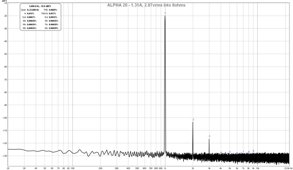
This is one of the most beautiful FFTs I have seen from a power amp running on a linear trafo based PSU with an F6 (CR-2xCRC) PSU, notice the dominant 2nd order and decreasing higher orders with 3rd order at least 10dB lower than 2nd order, and lack of any higher orders within noise floor of the measurement. The -130dB noise floor is the limitation of a consumer sound interface like the Focusrite. This is where a $40k AP system will allow measurements down to -150dB noise floor, but is that getting you more info that you need to debug the major things?
So here is what this system can tell you - when I run my F6 PSU in stereo, the extra current draw causes the AC line ripple to increase and this is clearly evident with the FFT. This says that if you want this clean performance in stereo, a dual 400VA 18vac trafo monoblock is needed.
Here is 2.79vrms into 8ohms in the second channel with the first one also running at 1.3amps bias:
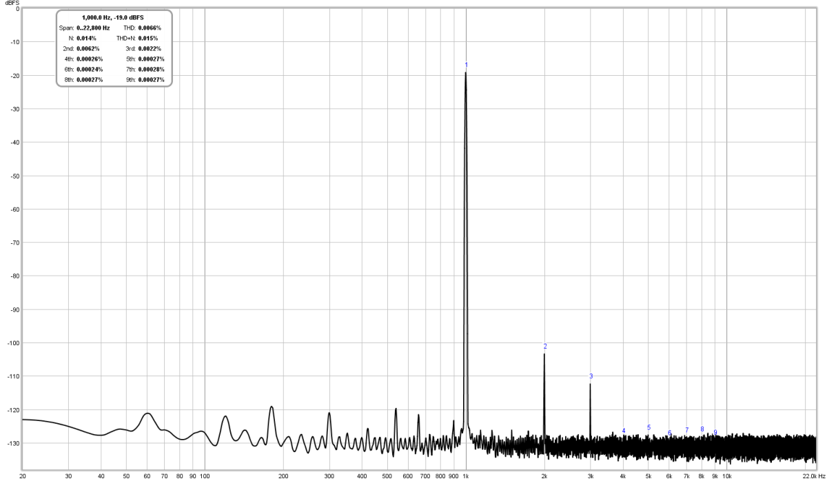
Actually it is still very good with only a +10dB increase but not flat as a board anymore. Just depends on your level of discomfort knowing that there are AC mains harmonics floating around in your signal. Most people would be very happy with this I suppose.
However, this is the 1.31amp bias case. For those chasing even lower THD and wishing to run 2.0amp bias as Hugh has designed it for, you definitely should do dual 400VA trafos and dual PSU's monoblocks.
After reviewing the above data again, and since I am still debugging the noise issue with the SMPS/DC boost/Cap Mx PSU option, if you are looking to proceed with a verified clean sounding and measuring ALPHA 20 at this point, I highly recommend to go the linear trafo route with the F6 PSU until I can solve the noise issue. But note that it is for 1.3amps bias (attained via 047R source resistors vs specified 0.33R).
Focusrite 2i2 (has similar front end on left and right so you can do stereo measurements):
Amazon.com: Focusrite Scarlett 2i2 (2nd Gen) USB Audio Interface with Pro Tools | First: Musical Instruments
You need these if you want to feed inputs with unbalanced RCA:
Amazon.com: 2 Pack CESS 6.35mm 1/4 Inch Stereo TRS Male Plug to RCA Female Jack Silver Adapter Connectors (#658: 6.35mm Stereo Male to RCA Female,2-Pack): Home Audio & Theater
25w 8ohm dummy loads:
uxcell 5 Pcs 25W 8 Ohm Wirewound Aluminium Housing Power Resistance Resistor: Amazon.com: Industrial & Scientific
REW software:
REW - Room EQ Wizard Room Acoustics Software
The above things lets you make a measurement like this - the ALPHA20 at 2.87vrms into 8ohms:
This is one of the most beautiful FFTs I have seen from a power amp running on a linear trafo based PSU with an F6 (CR-2xCRC) PSU, notice the dominant 2nd order and decreasing higher orders with 3rd order at least 10dB lower than 2nd order, and lack of any higher orders within noise floor of the measurement. The -130dB noise floor is the limitation of a consumer sound interface like the Focusrite. This is where a $40k AP system will allow measurements down to -150dB noise floor, but is that getting you more info that you need to debug the major things?
So here is what this system can tell you - when I run my F6 PSU in stereo, the extra current draw causes the AC line ripple to increase and this is clearly evident with the FFT. This says that if you want this clean performance in stereo, a dual 400VA 18vac trafo monoblock is needed.
Here is 2.79vrms into 8ohms in the second channel with the first one also running at 1.3amps bias:
Actually it is still very good with only a +10dB increase but not flat as a board anymore. Just depends on your level of discomfort knowing that there are AC mains harmonics floating around in your signal. Most people would be very happy with this I suppose.
However, this is the 1.31amp bias case. For those chasing even lower THD and wishing to run 2.0amp bias as Hugh has designed it for, you definitely should do dual 400VA trafos and dual PSU's monoblocks.
After reviewing the above data again, and since I am still debugging the noise issue with the SMPS/DC boost/Cap Mx PSU option, if you are looking to proceed with a verified clean sounding and measuring ALPHA 20 at this point, I highly recommend to go the linear trafo route with the F6 PSU until I can solve the noise issue. But note that it is for 1.3amps bias (attained via 047R source resistors vs specified 0.33R).
Last edited:
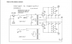
F6 PSU for your reference
I noticed that the F6 PSU is rather hard to find with a search, so here it is:

It has a subtle difference from basic F1 supply from Pass in that there is a split 2x RC on left and right for more stereo separation. Follow it exactly with all CL60 NTCs and topology of where grounding occurs, let no grounds be made inadvertently, control all connections to ground.
I noticed that the F6 PSU is rather hard to find with a search, so here it is:
It has a subtle difference from basic F1 supply from Pass in that there is a split 2x RC on left and right for more stereo separation. Follow it exactly with all CL60 NTCs and topology of where grounding occurs, let no grounds be made inadvertently, control all connections to ground.
Attachments
Some progress... after looking at some of the nice links in DC-DC converters that JPS64 posted I tried adding a common mode choke between the DC-DC converter and the cap Mx using 3 turns ea antiphase windings on a 1in diameter ferrite toroidal choke. I added a 1uF 630v MKT capacitor between the outputs of DC converter (really should be on the other side of choke but that would have required taking cap Mx out). Anyhow, it really reduced audible noise in one of the channels and less so in the other. I don’t know why they would be different. But you really have to press your ears to the cone to hear noise. I think for speaker listening it would be fine. I even skipped the output CRC. So it’s a pretty simple system at present with a very modest amount of actual capacitors. Largest are the 4700uF output caps at the cap Mx.
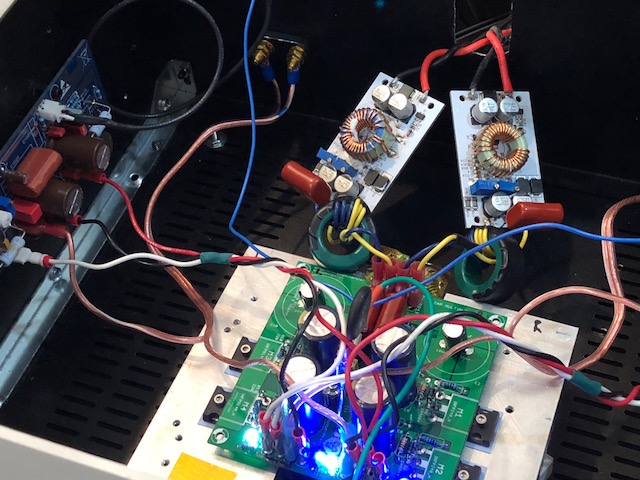
When I have more time, properly earth grounding the chassis and bolting the metal PCB DC converter to the chassis will probably help some more. Right now chassis is floating relative to earth ground.
When I have more time, properly earth grounding the chassis and bolting the metal PCB DC converter to the chassis will probably help some more. Right now chassis is floating relative to earth ground.
Attachments

Last edited:
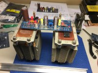
So this is what I came up with....
3/4”x3/4” Aluminium angle stock will run parallel and attach the two CPU coolers above the mounting bosses to create a rigid frame. Below(copper plate side) the ALPHA board will attach using only two of the four mounting holes.
3/4” Aluminium flat stock spanning both coolers will be used to clamp the MosFets to the copper surface as close to center as possible. Two of these ‘modules’ will be made. At this point I could make a pair of mono blocks or join them together into a single chassis. I have to figure out what type of power supply I will settle on. I’m going to try the smps route first.
Attachments
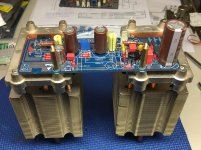
That looks very good Vunce. Excellent use of existing boss on cpu cooler to mount the board. I had to drill and tap two 4-40 threads on the aluminum frame of the CPU cooler to clamp the MOSFETs with L shaped aluminum clamp. If you can mount side by side PCBs and use just two CPU coolers that would be cool. Very nice work. You got some premium resistors there!
You got some premium resistors there!
Nothing but the best for AKSA/X/JP projects, lol!
I mocked up the SMPS—>DC booster—>Allo Cap Mx combo to an LM4780 chip amp to see if I was getting any hum/weird noises. Nothing, nice and quiet. I know it’s a totally different amp than the ALPHA, but wanted to make sure I wasn’t pushing the boulder uphill already
All you need is a sound interface like a USB Focusrite Solo (or 2i2 or 2i4) DAC/ADC or similar. The software (free) does it all. I use REW (normally used for measuring speakers). That’s how I make all the measurements shown here. The software and the sound card provides the sine generator. It’s a pretty cost effective solution and anyone building amps really should try it. Most people have a sound card so there’s no excuse really other than lack of will. Use the “generator” to make the tone and the “RTA” to capture the FFT. That’s it. You need an 8ohm power resistor dummy load. To start off, an 8ohm or 10ohm cement resistor 10w works fine. I use a 25w aluminum shell one bolted to a heatsink to do high power tests. But a 1w (2.83vrms) test is all you need. To look at PSU noise floor you don’t even need a generator. Make a circa 10:1 voltage divider between the dummy load and the ADC input to make sure an accident doesn’t fry your sound card’s front end. Something like a 2k and 22k make an 12:1 divider. The ADC opamp on Focusrite can take 20v (varies a bit with model) so you really are safe with just about any level with a divider. Without the divider you can do 2.83vrms up to 6vrms as peak to peak levels start getting close to saturation.
Thank you for the quick and very comprehensive reply! I checked Amazon and the Focusrite is about $200 here in Canada,a little too much for my budget right now.I was thinking of the probe(a cap and,pot and couple resistors) feeding into my pc's mic input along with the fft software.I have to dig up the probe construction details,they're out there,i've seen them.I do have a 10 ohm WW 10 watt load resistor(whoope).As I mentioned I do have a sine signal generator(HP).
- Home
- Amplifiers
- Solid State
- Aksa Lender P-MOS Hybrid Aleph (ALPHA) Amplifier