There is no such a thing as a "zero feedback amplifier", -at least one that uses transistors, mosfets or tubes for amplification.
Simply because transistors, mosfets and tubes are highly non-linear devices (=imperfect, useless devices for faithful amplification, which become useful only with the application of feedback). So feedback, local, global or multiple-nested, is required in order to linearize those imperfect devices.
Here is where all the anti-feedback arguments collapse!
But there are many other ignorance-based myths (or even promoted by makers of mediocre amps because they only do a minimum R&D as many buyers usually are mostly convinced by rumors rather than scientific facts), like "too much feedback raises odd and higher order harmonics and the amp sounds bad", "local feedback is good and global feedback is bad", etc.
Nothing of this is true for various reasons, but mainly because it all depends on the specific design which might be very different, NOT on the amount and type of a single parameter in a complex system. It's like judging a sportscar only by the amount of gasoline that runs through the gas pump, which of course would be incredibly stupid for obvious reasons.
The amplifiers' performance is what matters, which is the product of tens or hundreds of parameters, put together not randomly, but methodically after research. By focusing on a single parameter, or on the component types etc, you are missing the important thing, which is the actual measured output performance.
Last edited:
There is no such a thing as a "zero feedback amplifier", -at least one that uses transistors, mosfets or tubes for amplification.
Simply because transistors, mosfets and tubes are highly non-linear devices (=imperfect, useless devices for faithful amplification, which become useful only with the application of feedback). So feedback, local, global or multiple-nested, is required in order to linearize those imperfect devices.
Here is where all the anti-feedback arguments collapse!
But there are many other ignorance-based myths (or even promoted by makers of mediocre amps because they only do a minimum R&D as many buyers usually are mostly convinced by rumors rather than scientific facts), like "too much feedback raises odd and higher order harmonics and the amp sounds bad", "local feedback is good and global feedback is bad", etc.
Nothing of this is true for various reasons, but mainly because it all depends on the specific design which might be very different, NOT on the amount and type of a single parameter in a complex system. It's like judging a sportscar only by the amount of gasoline that runs through the gas pump, which of course would be incredibly stupid for obvious reasons.
The amplifiers' performance is what matters, which is the product of tens or hundreds of parameters, put together not randomly, but methodically after research. By focusing on a single parameter, or on the component types etc, you are missing the important thing, which is the actual measured output performance.
All true, and it gets repeated constantly. But people would rather listen to slick marketing jargon than engineers that actually design the equipment, because I guess salesmen know more than engineers.
At least once a week I try to point a newbie in the right direction right here on this website. Some of them just disappear; some of them have flamed me. A few listen. I say good luck if you want to design audio equipment based on sales brochures.
")
I have only visited the local upper crust hi fi store once. The salesmen aren't as bad as the big box salesmen (MORONS) but they still lay it on thick. I probably couldn't sell that stuff because I'd make the customer's eyes glaze over.
Probably someone will argue now that the base width modulation (Early effect) caused by the collector-base depletion region is a kind of feedback, and when you draw the same circuit with a triode they will argue that the effect of the anode on the current is a kind of feedback, and of course you use feedback to stabilize the bias point, but in my opinion it is not a feedback amplifier in the sense of Black's patent. At signal frequencies there is no feedback path around the active device.
Mainly only bias stabilization at the emitter, the emitter cap negates most of any signal feedback. I didn't explain in my first post that I was referring to output fed back to the input closed loop type of feedback. The Hfe curve could prevent runawy or excess gain by it's cliff like curve.
So far I like it best. Troubleshooting from a schematic and no voltage references can be difficult. Finding the origin of an error in a closed loop has been tricky for me personally. And I've seen others struggling with a packed circuit board in such a situation.
So far I like it best. Troubleshooting from a schematic and no voltage references can be difficult. Finding the origin of an error in a closed loop has been tricky for me personally. And I've seen others struggling with a packed circuit board in such a situation.
Last edited:
- Feedback is an ideal universal mechanism, only imperfections in the elements comprising the feedback loops contribute to imperfections in the output of the system.
- Feedback is everywhere, even inside electronic gain devices such as transistors, at electron and molecular level.
- Feedback requires some element outputting a magnitude which is the sum or difference (and/or other math operations) between other 2 or more magnitudes: The error amplifier. Feedback requires the output of the system to be fed back to input of error amplifier.
- Feedback happens inherently in every amplification circuit, even in follower configurations (the simplest case). The conditions for a follower to be unstable do exist, and can be created in practice.
- In linear electronic circuits: there are lower and upper practical limits for feedback. Lower NFB loops have to work with higher error magnitudes, requiring wider linear range of operation of error amplifier (and earlier amplification stages). Higher NFB loops encounter the opposite problem, error magnitude becomes low enough to be disturbed by other magnitudes, as by: parasitic inductive and capacitive coupling between circuit elements, noise floor of components, drifts in error amplifier characteristics due to temperature.
- In switched-mode amplifier circuits: feedback is employed too. "It does not need to be stable in order to be linear". The interest for switched-mode amplification arises when the practical limits of feedback are explored (the raw conditions where linearity improvement takes place).
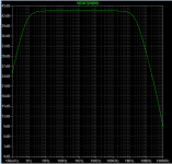
The following simulation pictures (based in a real circuit) show a class-D amplifier (modulator type: self-oscillating post-filter single-integrator) doing <0.007% 3rd harmonic at 5khz @ 50W @ 8ohm. The circuit is sized for up to 800W/2ohm output, using two N-ch TO-220 power MOSFET. This matches the performance of finest class AB projects shown in best solid state threads, while not being a stable NFB loop, but it is an unstable NFB loop constructed to be highly linear (this proves the 1st statement in this post).
Hi Eva
This is exactly right and a very good post.
BTW: In my experience with switching amplifiers (AKA Class D) you can also get a lot less Noise than in classic A or AB Amps.
BTW2: It seems like you are using about 400kHz (maybe a bit less) Switching Frequency.
I have designed my own Class D Amp, it's an all discrete design with "my own discrete comparator"
I'm using a bit higher switching frequency (and ofcourse my own discrete comparator) and I'm achieving a lot less THD at the same output level and in the 1ppm level at low outputlevel.
Cheers
Reodor
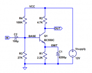
Here's an amplifier whose mid-frequency gain is roughly 160X (44dB).
Is this a feedback amplifier?
Why, or why not?
_
Yes it's feedback. But not much. Emitter resistors cause feedback, even if it's only the transistors internal emitter resistance. Show us the THD? Than figure out the gain and THD with a different emitter impedance, these will change the same as any other feedback scheme.
Don't take the comparator (differential amp) statement I made as official, I made that assumption and became confident enough to write that as if from official sources. Ot really should have been a question.
I was just going to say using negative feedback for linearization requires a precision comparator stage for the magic to work. Differential amp pairs on one die are a good idea for that. Sort of funny how the errors wiggle their way through the system until they stabilize at the comparator. There has to be some sort of high speed hunting and settling time, well above audio range.
I could not find but a few transistors even somewhat able to produce linear gain over the functional range without feedback. And they probably deteriorate with time and heat.
Here's an amplifier whose mid-frequency gain is roughly 160X (44dB).
Is this a feedback amplifier?
Why, or why not?
_
The emitter voltage of Q1 is almost 1.9V(12*(27/127)-Vbe). The emitter current of Q1 is 1.9/2.2(R1)=0.86mA, which means the equivalent emitter resistor of Q1 is 25/0.86=29ohm. The gain of Q1 is 4700(R2)/29=162.
In this situation, I'm sure Q1 has positive DC feedback because the negative coefficient of Vbe makes emitter current increasing. The positive feedback stops at the point where radiation of heat is equal to generation.
But I'm not sure AC feedback exists or not. It's true AC gain becomes large according to temperature rise because the equivalent emitter register becomes low. Temperature and the gain are a positive feedback to some extent. But AC feedback in an electrical circuit usually means between the input signal and the gain. I can regard temperature and the gain are positive feedback in a wide sense. The input signal doesn't have any feedback on the gain in this situation, unlike NFB of an OP amp. This has feedback or not is up to you, IMHO.
DC feedback yes (due to the emitter resistor), AC feedback no (due to the emitter res shorted by the capacitor) and you pay the price of no proper AC feedback with THD in the order of 15%. Let alone the cap coupling issues and the complete vulnerability to the load. In short, this aint a linear circuit and not a Hi-FI amplifier either.Here's an amplifier whose mid-frequency gain is roughly 160X (44dB).
Is this a feedback amplifier?
Why, or why not?
_
You're providing a social service thenAt least once a week I try to point a newbie in the right direction right here on this website. Some of them just disappear; some of them have flamed me. A few listen.
Well, someone has to do the dirty work!I say good luck if you want to design audio equipment based on sales brochures.
There are two options: you either let the market change you with minimum effort, or you do your best and you change the market.
I prefer the later. It's far more interesting, more challenging and more rewarding -in a general sense, not just profit. After all, there is always a market for true quality -if it's for me (a perfectionist), then it is for many more.
Last edited:
stocktrader200
Your posts are quite meaningless.
I see in another thread your understanding of Class D amps.
Have fun
Reodor
Your posts are quite meaningless.
I see in another thread your understanding of Class D amps.
Have fun
Reodor
Last edited:
Here's an amplifier whose mid-frequency gain is roughly 160X (44dB).
Is this a feedback amplifier?
Why, or why not?
_
This is an interesting circuit. I would consider this, not an amplifier, but a zero-cross detector or AC logic inverter. Reasons:
- Gain can change +/-25% warm to cold. Gain is not controlled.
- Output impedance is 4.7k in parallel with a variable resistance due to hFE being modulated by Vce and Ic. Output impedance is not controlled.
- Input impedance is low and changes with temperature (both due to variable base resistance and electrolytic ESR). Input impedance is not controlled.
In practical electronics (industry), circuits like that are avoided, chips like LM358 and LM393 were developed a long ago, to offer a more accurate result at lower cost (and lower part count), with DC precision down to millivolts, high input impedance and low output impedance. What are you going to do in signal processing with an amplifier having unpredictable gain? Controlling the speed or the temperature of something? Audio amplfiication that becomes louder as ambient temperature increases (ideal for mistraining the ears)?
Hi Eva
This is exactly right and a very good post.
BTW: In my experience with switching amplifiers (AKA Class D) you can also get a lot less Noise than in classic A or AB Amps.
BTW2: It seems like you are using about 400kHz (maybe a bit less) Switching Frequency.
I have designed my own Class D Amp, it's an all discrete design with "my own discrete comparator"
I'm using a bit higher switching frequency (and ofcourse my own discrete comparator) and I'm achieving a lot less THD at the same output level and in the 1ppm level at low outputlevel.
Cheers
Reodor
1ppm THD is an excellent mark for class D.
Of course higher part count can be traded for lower THD. However, one shall stop at some point, like 20dB below THD from HF drivers, past this point the element deserving linearization is speaker driver.
Yes, the long tail pair. I see the differential amp as an analog output comparator. Maybe I shouldn't have called it that but even comparator chips can be used as a low grade analog amp, and an opamp can be used as a low grade comparator.
Seems like I can be to the point, being a low count poster, have not been able to guess what level of people visit the forum. Better than I thought.
Anyway the input signal is the reference voltage and the other side of the differential amp is fed the output voltage to compare to the reference voltage (input signal). If the output is lower than expected, then in addition to the "fixed" gain, the diff amp will boost a bit more voltage to feed the drivers. So these amps I use could be seen as a signal modulated voltage regulator.
I figure part of the job of this sort of amp is to flatten out the response curve of non-linear components. In other words, my studies showed me they allow the use of less precision components AFTER the diff amp stage.
Probably why they are so popular.
The diff amp I am referring to runs very hot and has degraded and failed a few times. I recently found I had -0.45vdc output offset and replaced them before failure. Afterwards I have 0.04 vdc offset, polarity not remembered. I can blow across the diff amp pair and make the output flutter. Wild huh ? A wind speed sensor that weighs enough to make my back hurt.
What do you mean by precision comparator ?
Is this the long tail pair most amps and op amp have at the inputs ?
The only aging I know with a bjt ltp comes from input overdrive that can simply be avoided with two diodes shunting the inputs.
Last edited:
I remember now, it was at -0.04v offset after replacing the diff amp transistors. I was also watching it on the scope.
So if you want to make an analog wind speed sensor, use two matched transistors that run at maybe 140°F static temperature. Shield the wind input side of one transistor and leave the other open to the wind that is directed through a tube. Calibrate it with your car's speedometer on a calm day, or better night. The shielded transistor should have one side open to allow them to balance out to zero temperature difference in still air.
There may be a developed project of that configuration somewhere. Just for fun and transistor practice.
BTW, I know I should put a dual TO-92 heatsink on the audio amp transistors to balance and dissipate the temperature but didn't have anything on hand. I have plenty of time to get one. It takes years for them to fail.
Last edited:
One reason the Williamson amplifier sounded so good was the bandwidth was flat over the audible range with no feedback. When about 20db or so of feedback was applied the bandwidth went from a few HZ to 200 kHZ with the output transformer meeting D.T.N.'s specs. Negative feedback is a very useful technique in improving amplifier performance by reducing distortion. Sorry SETs.
This is an interesting circuit. I would consider this, not an amplifier, but a zero-cross detector or AC logic inverter. Reasons:
- Gain can change +/-25% warm to cold. Gain is not controlled.
- Output impedance is 4.7k in parallel with a variable resistance due to hFE being modulated by Vce and Ic. Output impedance is not controlled.
- Input impedance is low and changes with temperature (both due to variable base resistance and electrolytic ESR). Input impedance is not controlled.
In practical electronics (industry), circuits like that are avoided,...
Yes, but I have seen very nearly that plan in several old-old transistor amps.
Comparator? 20mV input will swing the output, 60mV will slam it. That's poor for a comparator. In most audio we have signals up near 1V, and yes it will "comparator" all the medium and loud parts to bent square waves. You even find this done in guitar distortion. (Usually one such stage is not enough for that.) This hyper-sensitivity, and *high* THD even before clipping, is the main problem.
It works fairly well as a mike preamp for dictation speech through a dynamic mike; all those $13 mono cassette recorders (and the low-price 3" reel-reel machines before them). Input levels rarely exceeded 1mV, distortion was tolerated, exact gain was moot because all $0.50 mikes and all talkers vary a lot in level.
I believe at least one Moving Coil phono head uses essentially this AC condition. Signal levels are tiny, so THD is tiny. Stage load is 47K so a 4.69K Zout is fine. Source is 10-100r so a 2K-4K Zin is fine. Temps around a phono are usually benign.
I don't follow the gain vs temp complaint. Yes, in a Military -50C to +100C environment the gain will swing like +/-25%. But this is an audio forum, primarily domestic audio, mostly in living rooms. +/-15C, 10C to 40C, is extreme for most of us listeners. I keep my rooms to +/-3C. The gain change is more like 1%, inaudible. (This stage as shown will not self-heat enuff to matter.)
Output impedance can be whatever, as long as it is not too high and you know what to expect. High Zout can sometimes simplify interstage networks. Here Zout is 99% controlled by the resistor tolerance.
Input impedance does go directly as hFE (and ESR only if the cap is crappy; it often was). However if you cascade such stages the low-hFE units suck more against the high Zout stage before it and voltage gain variation is lessened. (It is often better to design such things on current gain rather than the now-customary voltage gain.)
Zin and input overload level can be increased with a simple series resistor. This is an interesting form but tends to hiss.
"Is this feedback?" There's feedback in it, but not so you can design with it, and not so you can get "good" performance in most audio applications.
- Status
- This old topic is closed. If you want to reopen this topic, contact a moderator using the "Report Post" button.
- Home
- Amplifiers
- Solid State
- Why Let an Amplifier Sound Good when You can Force it to?