
You can replace both channels outputs with modern powerful TO220 devices. You place a flat metal bracket across the new replacements using the original holes to hold the bracket. It is a very simple and effective technique. Or start hunting on eBay for used devices or possibly NOS devices.
@mosfets Thank you for advice. I have selected following 2, would you be kind enough to confirm if I can replace them direct or any further modification is needed to fit them?
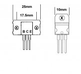
STMicroelectronics BD911 NPN Transistor, 15 A, 100 V, 3-Pin TO-220
STMicroelectronics BD912 PNP Transistor, 15 A, 100 V, 3-Pin TO-220
Many Thanks
STMicroelectronics BD911 NPN Transistor, 15 A, 100 V, 3-Pin TO-220
STMicroelectronics BD912 PNP Transistor, 15 A, 100 V, 3-Pin TO-220
Many Thanks
Don't forget that the driver transistors may have been damaged so when you fit replacement output transistors, bring the mains voltage up slowly and monitor the bias voltage drop.
BD911 | STMicroelectronics BD911 NPN Transistor, 15 A, 100 V, 3-Pin TO-220 | STMicroelectronics
BD912 | STMicroelectronics BD912 PNP Transistor, 15 A, 100 V, 3-Pin TO-220 | STMicroelectronics
They look fine and the pin outs are the same. Use a metal strip to pinch the transistor body, not the tab! to the heatsink and ensure good insulation and fresh heat sink compound.
Thank you once again for quick reply. My next questions may sound silly, so I apologize in advance.
The driver transistors, are they located on same board? I have checked all the transistors on same board and they work fine.
I was going to mount the BD911 and BD912 with paste and tighten them to heat sink with original screws. Do I need to put mica as well or just paste and screw on like old transistors were?
Explain exactly how the new BDxxx devices will mount to the existing 2SDxxx holes. Do you understand Snell when he says 'metal strip' or when I said 'bracket'? Another way to say it would be 'clamp'. Thermal pads or mica washers and grease are standard practice, so yes, do that proper.
If you pull that thing apart to repair it, why not change all of the pcb level electrolytics with new economic Elna's? If it was me, I would change all of the audio signal transistors and most certainly matched pairs for the pre-stage. I would probably recap all of it.
If you pull that thing apart to repair it, why not change all of the pcb level electrolytics with new economic Elna's? If it was me, I would change all of the audio signal transistors and most certainly matched pairs for the pre-stage. I would probably recap all of it.
Attachments
@Mosfets, JonSnell, my mistake, I now understand how to fit the replacement transistors. I am changing all the electolytics as well on the system. I have ordered parts and I will report back with outcome.
Thank you both, once again for your patience and guidance, I appreciate it.
Thank you both, once again for your patience and guidance, I appreciate it.
bad news, last night completed the rebuild and it is still blowing fuse when reaching 110v. I am pretty certain it is the transistor mounting which is causing issues.
I have drilled a 2mm hole in old heat sink and used a self tapping screw through the plastic collar, applied thermal paste, insulator and then paste again. Tightened it lightly.
When checked for continuity there is continuity on middle pin only with heat sink and rest of metal casing but pin 1and 3 have no continuity with heat sink.
Can anyone please confirm that I have done this correct? I have recapped all the boards with correct electrolytic caps and have triple checked the polarity. I am at a loss as to why the 5amp fuse keeps blowing on switching the unit on.
The middle tab of your new devices should be the collector. If the the collector for NPN and PNP are in contact to each other via the heat sink, then you are shorting the minus and plus rails of the power supply together. Re-think what it is you are doing. Try to understand the devices and where they 'live' in the circuit and the physical housing. Look at the collectors in the schematic and see what they are 'touching' or are connected to.
If you don't have a a variac, please build a simple dimmer switch light bulb start up box thing. Google it. I never needed one so somebody can point you to a simple one to build. It will help you and save on fuses and smoked out parts.
...and good luck!
If you don't have a a variac, please build a simple dimmer switch light bulb start up box thing. Google it. I never needed one so somebody can point you to a simple one to build. It will help you and save on fuses and smoked out parts.
...and good luck!
- Status
- This old topic is closed. If you want to reopen this topic, contact a moderator using the "Report Post" button.
- Home
- Amplifiers
- Solid State
- Trio KA-305