Hi,
I have this amplifier but it has a problem now with DC on speaker output.
When i turn voulume up i see with my voltmeter there is DC voltage on outputterminals.At 40% volume i hear rele clicks and DC drops to zero.
Is amplifier totally damaged or is it the preamppart.
I need a servicemanual to find out were DC occurs in signal.
Any good advice?
Thanks,
Hi,
Thanks for Your reply to my post.
Thing is i do not think about transistors broken right now.
Yesterday when starting my investigate i could listen to music coming out from headphoneoutput.I did not use any speakers.Then when turning volume to approx. 40%
Output relays clicks and no more music coming trough any channels R/L.
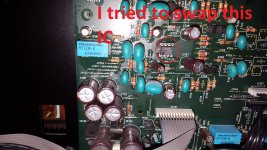
Then i thought it must be a common failure for both channel so i swapped a opamp on preamp board (JRC082BD) with a OPA2134 just to see if it was thisone.Now when i put back JRC082BD again i do not hear Output relays after powerup.This means i now have constant DC on output.So far there has been no smoke and no burned parts.The failure is common for both channels.I also removed signal cables from Preamp but Output relays do not click when powering up amplifier.
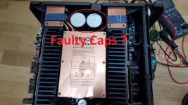
Could it be faulty or leaky Capacitor in powersupply rail ?
Regards,
Bjorn
Thanks for Your reply to my post.
Thing is i do not think about transistors broken right now.
Yesterday when starting my investigate i could listen to music coming out from headphoneoutput.I did not use any speakers.Then when turning volume to approx. 40%
Output relays clicks and no more music coming trough any channels R/L.
Then i thought it must be a common failure for both channel so i swapped a opamp on preamp board (JRC082BD) with a OPA2134 just to see if it was thisone.Now when i put back JRC082BD again i do not hear Output relays after powerup.This means i now have constant DC on output.So far there has been no smoke and no burned parts.The failure is common for both channels.I also removed signal cables from Preamp but Output relays do not click when powering up amplifier.
Could it be faulty or leaky Capacitor in powersupply rail ?
Regards,
Bjorn
Attachments

Last edited:
Hi,
Could it be faulty or leaky Capacitor in powersupply rail ?
Regards,
Bjorn
Unlikely unless they are really bad.
Have a look with a scope.
Headphones and very small speakers may well sound ok even when the output transistors are blown. The driver or even pre-driver transistors can simply play on directly via the base-emitter junction of the shorted or open output transistor(s) - up to a point when the current demand is too great and they too, blow. If you do have a significant DC potential at one or both + output terminals though, I would not try this again - fit a large value capacitor inline to isolate the DC and protect the 'phones.
You don't specify how much DC is present at the output terminals but it can't be the full rail voltage if your headphones haven't burnt out yet. The speaker/headphone relay will usually disengage (drop out) when the DC potential at the output reaches about 1V. This is more likely the voltage you refer to. As you are probably varying the DC level also with the volume control, it would seem to arise from the stages before it but for both channels, it's an odd situation. Try measuring and reporting these voltages. This makes the problems simpler for us to understand, especially when there is no schematic")
You don't specify how much DC is present at the output terminals but it can't be the full rail voltage if your headphones haven't burnt out yet. The speaker/headphone relay will usually disengage (drop out) when the DC potential at the output reaches about 1V. This is more likely the voltage you refer to. As you are probably varying the DC level also with the volume control, it would seem to arise from the stages before it but for both channels, it's an odd situation. Try measuring and reporting these voltages. This makes the problems simpler for us to understand, especially when there is no schematic
I agree with You both but normally when output transistors are blown you can observe it fysically by some damage or even smell.Here i have nothing and when i measure these output transistors they looks fine , none of them are shorted or open.
Yesterday when i turned volume up i could see voltage rise from 0V DC to about 2,5V DC when relay turned outputterminals off.
Were can i measure offset voltage when output is switched off by relay?
Yesterday when i turned volume up i could see voltage rise from 0V DC to about 2,5V DC when relay turned outputterminals off.
Were can i measure offset voltage when output is switched off by relay?
Attachments
Last edited:
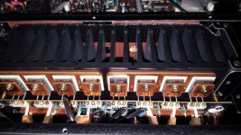
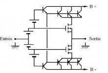
I think I can assume this is one of the 99.9% typical Japanese Amplifiers with an Emitter-Follower output stage design. So, you can measure the output node of these directly at the junction of the large emitter resistors of the output transistors - or either end of the output coils will suffice if, for some reason, you can't get access to the copper side of the PCB and the relay connections etc. Take car, use clips rather than bare probes etc. when metering live power amplifiers as like a lot of guys, you may wind up replacing more than one set of semis plus a few sundries as well.
However, as suggested, you are now looking for the origin of the DC that is adjustable via the volume control, which logically, would mean it arises before the power amplifier and control - often in the late stages of the preamp. My guess for the source now, would be leakage voltage from any electrolytic bypass or coupling capacitors which then adds to the signal. That's only one possibility with DC coupled amplifiers though. You'll have to trace out the preamp signal path for yourself to locate the suspects because there does not appear to be an online free service manual to refer to. If this gets too complex for you, rather than spoil a good product with too much trial and error, I suggest you get professional help. It can be surprising how easily a pro. can navigate their way through a sea of small parts and quickly find the problems with relatively low costs in time and parts. A messed-up amp. could be a write- off though.
If the power amplifier is fine, you should be able to check it by disconnecting the preamp from the amplifier (perhaps via links on the rear panel?) and the problem should disappear, apart from noise due to an open circuit input - you could ground that via say, a 10k resistor for silence. Remember though, disconnect speakers etc. when the amplifier is free to blast at full volume and destroy all, including itself.
Regarding burnt semis - Drivers, predrivers or any small-signal semi may blow without sign or smell. Over many years, I've found there are as many exceptions as there are "rules" that we make about faults.
DC on Output
I found out there is no common preamp in this amplifier, only a selectorboard with a Phonostage on it.Does it sound likely that both outputrelays is activated even if DC offset only occurs on Left channel?.They have seperate powersource but common Protectcircuit as far as i can tell.If there is DC offset ,will i measure this also on inputterminals as a "feedback"?.
Thanks for all help.
Regards,
bjorn
I think I can assume this is one of the 99.9% typical Japanese Amplifiers with an Emitter-Follower output stage design. So, you can measure the output node of these directly at the junction of the large emitter resistors of the output transistors - or either end of the output coils will suffice if, for some reason, you can't get access to the copper side of the PCB and the relay connections etc. Take car, use clips rather than bare probes etc. when metering live power amplifiers as like a lot of guys, you may wind up replacing more than one set of semis plus a few sundries as well.
However, as suggested, you are now looking for the origin of the DC that is adjustable via the volume control, which logically, would mean it arises before the power amplifier and control - often in the late stages of the preamp. My guess for the source now, would be leakage voltage from any electrolytic bypass or coupling capacitors which then adds to the signal. That's only one possibility with DC coupled amplifiers though. You'll have to trace out the preamp signal path for yourself to locate the suspects because there does not appear to be an online free service manual to refer to. If this gets too complex for you, rather than spoil a good product with too much trial and error, I suggest you get professional help. It can be surprising how easily a pro. can navigate their way through a sea of small parts and quickly find the problems with relatively low costs in time and parts. A messed-up amp. could be a write- off though.
If the power amplifier is fine, you should be able to check it by disconnecting the preamp from the amplifier (perhaps via links on the rear panel?) and the problem should disappear, apart from noise due to an open circuit input - you could ground that via say, a 10k resistor for silence. Remember though, disconnect speakers etc. when the amplifier is free to blast at full volume and destroy all, including itself.
Regarding burnt semis - Drivers, predrivers or any small-signal semi may blow without sign or smell. Over many years, I've found there are as many exceptions as there are "rules" that we make about faults.
Found Scematic
This amplifier has not been repaired yet.I putted it "on hold" for 2 years. Now i found scematic for an similar model called PMA-SA11.
It has the same protect board as my PMA S10II so now i have started to investigate again.
What i found out so far: My speaker relays do not activate after turning on amplifier.I have measured DC before this relays coming directly from outputtransistors, Zero voltage after power up (normal).So far i think my problem is located with this protector board.I have zero voltage (DC) on base of TR614.TR618 is operating with DC level 3V on base after power up syclus. So i beliewe that fault is before TR614. Anyone here who could help me trace it down?
Thanks,
I could not place scematics directly as file was to big.
Link to download: Denon PMA-SA11 - Manual - Stereo Integrated Amplifier - HiFi Engine
- Status
- This old topic is closed. If you want to reopen this topic, contact a moderator using the "Report Post" button.
- Home
- Amplifiers
- Solid State
- Denon PMA-S10II