Hi,
when I try to use low power Mosfets (e.g. IRF510) with currents of 10mA to 50ma (e.g. in the first stage of a power amp), I see that the transconductance is MUCH lower than what theory and Spice are telling me. I had the hope that by using a bigger device with a higher K, transconductance and linearity are better, but measurements don't confirm this.
I searched the Internet and could not find any explanation. I don't think that an IRF510 with Id=10mA is in the subthreshold region. And in the data sheets the low current region seems never to be shown in the transfer characteristics.
Nelson Pass often uses bigger Mosfets than necessary in driver sections, so he should know about this behaviour. Who else has seen this?
Cheers,
Gerhard
search terms:
and the parasitic C of oversized devices ran at tiny currents slows them down, increases high frequency distortion
Hi Rick,
Here are the models that I recommend using. These VDMOS models use the LTspice parameter ksubthres to model sub-threshold conduction. I did the original simulations with ordinary VDMOS models and got sim results worse than my measured real-world results. I was actually in the process of creating these models today so that when I (finally) post the .asc it will simulate with these improved models.
Cheers,
Bob
and the parasitic C of oversized devices ran at tiny currents slows them down, increases high frequency distortion
Last edited:
Sub-threshold behavior
MOSFETs used in IC design exhibit the transfer characteristics of a bipolar transistor (although still infinite beta) when they are run well below threshold, which is to say, and exponential relationship between Vgs and Ids.
I don't know if such behavior extends to sub-threshold operation of the big mosfets you're looking at, but it might be interesting to plot Vgs versus Ids for small values of Ids and see.
If you want high effective gm in the 10-50mA range one solution is to cascode a logic level SMT MOSFET with a heatsinkable part like the IRF510. The SMT part can have almost as high gm as a bipolar transistor but has very low power rating. Hence the need for the cascode. Look up Toshiba SSM3K339R - it has the best gm curve I've seen for any MOSFET but its in SOT-23.
I don't think that an IRF510 with Id=10mA is in the subthreshold region.
Datasheet spec: 1.5 S at 2 A
Quadratic model: transconductance proportional to square root of current -> theoretically 106.066017 mS at 10 mA
Current divided by theoretical transconductance: 94.280904 mV
When the ratio of current to transconductance is >> 2 n kT/q, with n the subthreshold slope factor, the MOSFET is in strong inversion, when it is << 2 n kT/q it is in weak inversion. Your MOSFET is somewhere in between, so in the notoriously difficult to model moderate inversion region.
I designed a TO-92 size mosfet into a circuit running at 10mA. It turned out the real gm was only 10% of what the data sheet implied. Caused me some confusion for a while. In the end I used a bipolar. Much better.Who else has seen this?
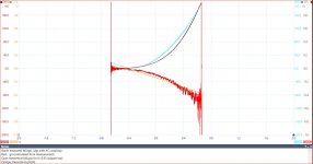
I have now measurements with IRFD110 (similar to IRF510), with Ugs=12V and up to 200mA, showing that it definitely does not follow square law in this region:

The gm charts are shown negative for better visibility. The horizontal axis is moved by using AC coupling, the Vgs=VTH point is located at -0.4V The theoretical charts are made with K=0.35, which is much smaller than K=0.56 (1.5S at 2A).
I will repeat these measurements with TO92 devices, expecting that they behave differently.
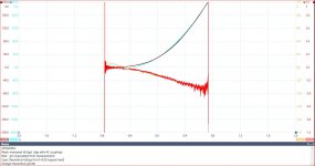
Here the same with ZVP4306A, a plastic case device from (former) Zetex. Here square law is much better followed, as can be also seen from the Gmd(Id) line being much straighter.

What I have learned from this: There is no benefit from oversizing a device, it results only in higher capacitances and therefore degraded high frequency performance.
With smaller devices there remains the challenge of dissipation (when we don't resort to cascoding, as abraxalito proposed - thanks for the hint!). Has somebody experience with cooling of plastic cases (TO92 or similar) with small clips? I expect that 1.5 to 2W should be possible.
Interesting results- thanks for the info.
I have not made any systematic measurements - perhaps another item you may want to add to your "to do" list (or not). I have used simple aluminium angle to clamp TO-92's to a standard heatsink, and have not overheated as a result.
Typical Rth j-amb is abnout 200K/W. My guess is that because plastic is such a poor conductor that I would not run them at more than 2x (thus I expect 100K/W Rth j-c) , but to check I would also have to measure the performance. You can "easily" measure the Vbe for a device with and without a heatclip to check the temperature rise (with a high impedance probe/amplifier/multimeter of course).
I have now measurements with IRFD110 (similar to IRF510), with Ugs=12V and up to 200mA, showing that it definitely does not follow square law in this region:
View attachment 656892
The gm charts are shown negative for better visibility. The horizontal axis is moved by using AC coupling, the Vgs=VTH point is located at -0.4V The theoretical charts are made with K=0.35, which is much smaller than K=0.56 (1.5S at 2A).
I will repeat these measurements with TO92 devices, expecting that they behave differently.
Could you please explain what your measurement set-up is? An IRF510 biased at a Vgs of 12 V would draw a lot more than 200 mA when it is biased outside the triode region (Vds > Vgs - Vth), as amplifying devices normally are.
Is the transconductance proportional to drain current for Id << 10 mA, like it should be in weak inversion?
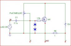
Sorry for the misspelling. It should read Vds=15V, not Vgs. This is the setup:

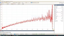
Gm as a function of Ids (for K=0.56, which is the datasheet value):

For small currents it is not totally linear but definitely more so than the theoretical Gm for square law. But the difference (e.g. 0.1S instead of 0.15S at 20mA) is not dramatic. Actually IRFD110/IRF510 is still a small device. Unfortunately there is much noise in the calculation due to the differentiation.

Gm as a function of Ids (for K=0.56, which is the datasheet value):

For small currents it is not totally linear but definitely more so than the theoretical Gm for square law. But the difference (e.g. 0.1S instead of 0.15S at 20mA) is not dramatic. Actually IRFD110/IRF510 is still a small device. Unfortunately there is much noise in the calculation due to the differentiation.
John:
I have now made a test with ZTX653 (case e-line, Ptot=1W @ 25°C, 5.7mW/K degradation) at 0.96W (80mA, 12V). Measured Vbe:
- free air (20°C): 370mV
- with small heatclip (10x15mm): 450mV
- mounted with the flat side on a big heatsink: 586mV
This results in a cooling (assuming that the 2mV/K are valid in the hole temperature range) by
- heatclip: (450-370mV)/2mV/K = 40K
- big heatsink: 108K
With the heatclip the limit is 1W+5.7mW*40K=1.23W and with an (unrealistically) big heatsink 1.61W.
These are not big improvements, although the surface of the case is much cooler with the heatclip. You are right, the plastic is the real problem. Therefore we must look for cases with an exposed metallic area like SOT223 or rely on cooling through the leads of SMD devices.
- Status
- This old topic is closed. If you want to reopen this topic, contact a moderator using the "Report Post" button.
- Home
- Amplifiers
- Solid State
- Transconductance of Mosfets at low currents