Happy New Year to all!
I have a Yamaha HS80M monitor that turns on but makes no sound until I move the ROOM CONTROL switch (S2 on the input PCB) back and forth. After a few wiggles (with popping sound each time the switch changes position), it turns on.
I took out the input PCB and injected some isopropyl alcohol inside this switch and wiggled it but the problem is still there.
I do have the schematics. There is a network of resistors and caps and an op-amp associated with this switch. The problem is that it is all SMD.
I was going to remove the switch S2 (3 position selector, 5 pin) for disassembling and cleaning but after checking it out with a magnifying glass I had second thoughts...
Any ideas? Anyone having similar problems with this monitor?
Phantombox
PS: I forgot to mention that these monitors are working in a somehow damp environment, all metal parts (speaker casings and brackets on circuit boards but not the PCBs) show signs of moisture.
The joints had to be looked at...
I think the only sure fire to attack this now is to follow normal fault finding procedure which means applying a known signal and tracing it through with an oscilloscope.
Is moving the switch really 'fixing' the issue, or is it a red herring as they say. You need to trace the signal and see where it goes astray.
Hello Mooly.
I got the monitor working again, using the "red herring" way.
Unfortunately my oscilloscope is not working and I haven't found someone to fix it. I do have access to another one that works with a laptop via an interface, but the guy who owns it is on holiday.
This may take a few days...
I got the monitor working again, using the "red herring" way.
Unfortunately my oscilloscope is not working and I haven't found someone to fix it. I do have access to another one that works with a laptop via an interface, but the guy who owns it is on holiday.
This may take a few days...
signal tracing doesn't require an oscilloscope my old Eico 147 does a great job at letting me know where signal is or isn't! (or any medium gain amp like an lm358 can work as a "tracer" in a line level circuit) and the thing i like about it is i don't have to look away from what i'm doing (reducing slip ups)i can hear where things get lost.
or injecting signal from the output amp and working back through to the input should help narrow down the section with the fault.
or injecting signal from the output amp and working back through to the input should help narrow down the section with the fault.
Hi Turk.
Those good old days... Unfortunately I don't have one of those tube loaded EICO tracers.
I guess I could just use any guitar amp: unbalanced cable plugged to the amp and the other end instead of a guitar I would connect ground of cable to ground of monitor and tip with a wire as my "tracer"...
Would this actually work?
you don't need some thing as hi gain as a guitar amp, any line level amp you have (think old stereo amp) make a probe with an old RCA cable with an alligator clip for ground and and old meter probe to the signal line and your in business. in the "old days" i would bypass the rf section of a portable transistor radio for a signal tracer.
Last edited:
I kinda narrowed it down.
When disconnecting the input pcb, there are +14.85V and - 13.75V on the pins coming out of the power pcb. When I connect the input pcb back there are +14.85 and -0.8V on the pins, so the problem should be on the -V power on the input pcb.
I can "jumpstart" the monitor and then the voltages are ok (well, +14.85 and -13.75 is not optimal but it doesn't induce any noticeable noise).
Part of the schematics I have are in the post "Yamaha HS80m Mod Help~" send on 6th March 2012, 03:29 AM by "xqtion". (Yamaha HS80m Mod Help~)
I do have the complete service manual but I can't figure out why I can't attach it at the moment.
I do have the complete service manual but I can't figure out why I can't attach it at the moment.
That diagram shows all the opamp circuitry fed from -/+15 volts.
It sounds like you either have a problem on the signal board that is pulling the voltage down or there is something odd happening in the power supply.
You need to measure the power supply voltages when the unit is in the faulty state and see why the voltage is missing. Normally if there is a short then something would be getting hot such as voltage regulator.
Post a diagram of the power supply that feed this board and we'll take a look.
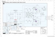
Get the unit in the faulty condition so there is only the -0.8 volts you mentioned, and then without disturbing anything check the voltage on the 7915 regulator marked in red.
Be very careful not to short any pins while testing. It might be easier to do a check on the voltage on each end of D803 that is across the reg. You should have minus 15 volts on one end and something higher than -20 on the other.
If the voltage is missing then you have a basic problem around the reg such as a dry joint.
If the voltage is present on the reg but not present on the board it goes to then you have a break somewhere.
Drys on the reg could be a real possibility.
The fact is that I can "jumpstart" the monitor by creating a brief short between input and output pins on the 7915 regulator. And given the fact that the monitor immediately comes to life means that there cannot be a break. I already re-soldered al pins surrounding the 7915.
Can I be that D803 is faulty? Can I use any other diode instead of the 1SS133? I do have some 1N519 and some 1N4148 diodes...
Can I be that D803 is faulty? Can I use any other diode instead of the 1SS133? I do have some 1N519 and some 1N4148 diodes...
The diode is unlikely to be faulty but I would change it anyway (any 1 amp 100 volt type such as a 1N4002 is OK, not a 1N4148 though as that is to small) and also change the regulator. If the 1N519 is suitably rated then use those.
It is also possible the regulator itself is faulty and not starting correctly. Odd things can happen if one rail appears before the other, its a well documented issue but something I have never encountered in real life.
Also look at the 4700uF reservoir caps. If one was deteriorated then it would imbalance the start up rise time of the rails maybe locking the regulator out.
Another thing you could try would be adding two more reverse biased diodes, one across each of the rails from the regulators. That also helps prevent the regulator seeing any odd start up conditions and momentary reverse voltages at start up.
Its an odd issue, one that is written about and yet one that I have never experienced.
 excellent news.
- Status
- This old topic is closed. If you want to reopen this topic, contact a moderator using the "Report Post" button.
- Home
- Amplifiers
- Solid State
- Yamaha HS80M Problem with switch on input PCB