That definitely sounds suspect.
Before you replace it though you need to check other possibilities.
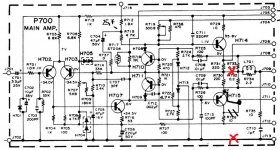
1/ You should have the supply voltage on R713. You also need to check this resistor is OK and not high in value or open circuit.
2/ Check C702 isn't leaky or short.
If those are OK and you have voltage on one end of R713 then change the zener. It will be an 18 volt 0.5 watt part.
Before you replace it though you need to check other possibilities.
1/ You should have the supply voltage on R713. You also need to check this resistor is OK and not high in value or open circuit.
2/ Check C702 isn't leaky or short.
If those are OK and you have voltage on one end of R713 then change the zener. It will be an 18 volt 0.5 watt part.
We need to know three things.
1/ That the resistor is OK and measures 1k out of circuit.
2/ That the full rail voltage is applied to the right hand side (as drawn on the diagram) of the resistor.
3/ The voltage across the zener. This is the same as reading the voltage on the other side of the resistor. It should be 18 volts.
If you have supply voltage going into the resistor and the zener voltage is low then you must change the zener.
Based on what you have said so far the zener is suspect.
One step at a time.
Replacing the zener should have brought the 18 volts back. Yes ?
You now need to recheck the DC offset at the output and make sure it is less than 100mv. If it is then the amp should hopefully work.
Low bias wont do any harm at this stage, get the amp working first.
Replacing the zener should have brought the 18 volts back. Yes ?
You now need to recheck the DC offset at the output and make sure it is less than 100mv. If it is then the amp should hopefully work.
Low bias wont do any harm at this stage, get the amp working first.
Hi Mooly, This is what we got the left channel came to life you can hear the station but their is a hum on it, the right channel is ok. I checked the DC offset (from the speaker terminals correct??) if so i have 2.1v on the right side( cannot get it lower on the right) 0v on the left I got 35v on the P800 board
There seems to be a lot of random things going on ")
I thought the right channel was OK and had no offset (going back a few days).
Lets concentrate on the left channel.
Did replacing the zener bring the 18 volts back to the correct value ? You haven't answered that
And still on the left channel only, you are sure the offset is close to zero ?
Also, does the bias adjust pot work OK on the left channel and allow the bias current to be varied ? This is the one we check by measuring the voltage across the 0.2 ohm resistors.
All those three things have to be OK before going further.
Assuming they are OK, Do you hear the hum as the volume control is turned down ?
If the hum reduces with volume, do you get the hum if you use a line level input such as a CD player ?
Remember, this is all for the left channel. Forget the right channel for now.
I am sorry for jumping ahead just got a little excited LOL Tomorrow i will check the voltage of the Zener diode, check the offset on the left side only, the adjustment pot is extremely and i mean extremely sensitive i got the voltage down to 10.0mv but it started to go down after some time( with in 1-2 minutes) can i use Deoxit on that trimmer ?? Still on the DBT when i go to adjust that pot the slightest movement makes the bulb go from dim to bright, that does not seam right does it?? Back to you tomorrow
Many thanks for your help
Many thanks for your help
- Status
- This old topic is closed. If you want to reopen this topic, contact a moderator using the "Report Post" button.
- Home
- Amplifiers
- Solid State
- New Project Marantz 2250b