Hello friends,
Three years ago I acquired a Denon SA-3350 integrated amp like this:
Some months ago one channel stopped working... supply rail DC voltage at output... output stage KO.
Problem with this amplifier is that the power stages are the famous STK hybrid ICs which are difficult and expensive to get and you can't tell at first if it's an original part or a counterfeit one unless you dismantle the unit or X-ray the IC.
So, after some research I decided to desolder the two STK-078 ICs and replace the power stages with one of the Yuan Jing Audio modules:
Yuan Jing Audio - LM1875 2.0 Fever Amplifier Board [25W + 25W] - USD $20.80
This module, based on LM1875T fits into my cabinet perfectly and provides speaker protection.
I thought it was worth trying to repair the amp for the price of this module.
This is the moduie installed into my unit:
I didn't found schematics for this amp so I've connected the input of the module (via shielded L-GND-R cable) to the common point of the bass and treble cursors and soldered the GND lead the closer I could to L and R leads:
The module worked great, the volume and tone controls worked as expected but an annoying buzz comes out of the speakers with no input present and volume at minimum.
If I short GND with L and/or R at the input connector of the module PCB the noise ceases completely but, If I short GND with the leads where the leads are soldered to the preamp, the noise is reduced a bit but still very noticeable. This suggests me the existence of a ground loop problem.
Here is an oscilloscope capture of one output channel. The other channel behaves similarly:
Note the spikes are spaced at mains frequency (50Hz).
I would appreciate some tips to try overcome this problem (more appropriate points to solder the input leads to, adding/removing ground leads, etc.)
I'm having fun with the project and I think this is a great opportunity for me to learn something new with your unvaluable help and experience.
Thank you very much.
Three years ago I acquired a Denon SA-3350 integrated amp like this:
An externally hosted image should be here but it was not working when we last tested it.
Some months ago one channel stopped working... supply rail DC voltage at output... output stage KO.
Problem with this amplifier is that the power stages are the famous STK hybrid ICs which are difficult and expensive to get and you can't tell at first if it's an original part or a counterfeit one unless you dismantle the unit or X-ray the IC.
So, after some research I decided to desolder the two STK-078 ICs and replace the power stages with one of the Yuan Jing Audio modules:
Yuan Jing Audio - LM1875 2.0 Fever Amplifier Board [25W + 25W] - USD $20.80
This module, based on LM1875T fits into my cabinet perfectly and provides speaker protection.
I thought it was worth trying to repair the amp for the price of this module.
This is the moduie installed into my unit:
An externally hosted image should be here but it was not working when we last tested it.
I didn't found schematics for this amp so I've connected the input of the module (via shielded L-GND-R cable) to the common point of the bass and treble cursors and soldered the GND lead the closer I could to L and R leads:
An externally hosted image should be here but it was not working when we last tested it.
The module worked great, the volume and tone controls worked as expected but an annoying buzz comes out of the speakers with no input present and volume at minimum.
If I short GND with L and/or R at the input connector of the module PCB the noise ceases completely but, If I short GND with the leads where the leads are soldered to the preamp, the noise is reduced a bit but still very noticeable. This suggests me the existence of a ground loop problem.
Here is an oscilloscope capture of one output channel. The other channel behaves similarly:
An externally hosted image should be here but it was not working when we last tested it.
Note the spikes are spaced at mains frequency (50Hz).
I would appreciate some tips to try overcome this problem (more appropriate points to solder the input leads to, adding/removing ground leads, etc.)
I'm having fun with the project and I think this is a great opportunity for me to learn something new with your unvaluable help and experience.
Thank you very much.
Very short duty cycle - looks like charging pulses from the power transformer wiring being picked up by the input stage wiring so yes, wiring, grounding or shielding is likely wrongly positioned or connected. The location of the new board (right above the fuses and possibly the power supply there) might have something to do with this.
Last edited:
Try lifting the shield where you connected to the original board. Is the shield grounded on the new board?
Craig
The cable used is like this one:
Yuan Jing Audio - Shielded Audio Cable JST-XH-2.54-3P AWG28 - USD $0.40 - Cables
I assume the shield is the central conductor. I've desoldered the central conductor at the original board and noise increased a bit.
In the new board this connector is tied to ground too.
You could try a 47pf from the 1875 boards inputs to ground, and see how that affects things.
I've tried but had no improvement. I saw this hint in the LM1875T datasheet for curing high frequency oscillation issues.
Might try putting the lid on the amp and see if that cures it too.
No differences.
I have an amp that does that, I just try not to use it without any inputs connected.
")
Very short duty cycle - looks like charging pulses from the power transformer wiring being picked up by the input stage wiring so yes, wiring, grounding or shielding is likely wrongly positioned or connected. The location of the new board (right above the fuses and possibly the power supply there) might have something to do with this.
I've found a wiring diagram that seems similar to my amp's. It seems there are two power supplies, one split, the other not. The new board is placed above the caps of the single supply. The fuses are from the speaker lines.
Having the leads floating in the air is quieter than touching the input with the chasis.
I've discovered that tying the input to the cursor of the volume pot makes the noise be progressively reduced when turning up the volume knob.
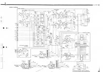
I attach the schematics I've found (very similar topology to my amp's as I can tell).
Thank you for your answers
Attachments
I Would take the out after the Volume pot and not at the bass / treble midpoint, unless the volume pot is mounted before tone controls. After Balance pot perhaps ? How are You powering the module ? Amp PSU in parallel with module PSU ? Too large capacitance producing high ripple? Is GND connected to amp Star ground too ? Disconnect the audio input from the module without shorting inputs and verify if the buzz is still there. If it is, You have a shielding / Interference problem. If it is hum You have a PSU filtering problem. You can try a 10K on the module inputs to ground in order to force them low without signal.
Last edited:
I remember a case like this a year or so back where the cure was to fit the bottom panel of the amplifier back into position. Your new module looks up in the air where it is installed well clear of any shielding effect from the case which would be close to the bottom of the original board. If you have any scrap metal lying around you could fit a test lead with alligator clips either end one to the metal and the other to the main chassis and put it below the new board to see it this helps.
Thank you for your answers!
I've spent a couple of hours with the amp and did some experiments.
Let me put some notes first: the new power stage module has its own power supply circuit so I'm powering it directly to the AC 26-0-26 outputs of the transformer. The original board seems to have two power supply circuits: one split (AC 26-0-26), one single 33VAC. There is another winding (2.9 VAC) for the bulbs. The two STK-478 original output stages were removed from the original board. Those ICs were powered by the split supply. I suppose the preamp section of the original board is powered by the single supply. So we have two split supplies in parallel (the old one which is working unloaded now since I removed the STKs, and the new module's) and the single supply powering those little transistors.
In the first experiment I've connected the new board inputs to the jack of my mobile phone. No buzz. For this experiment the module was in the place you saw in the photos: flying closely above the filter caps of the old PS.
In the second experiment I've detached the new board and placed it several centimeters above and perpendicular to the old board. Buzz still there. No improvement.
Placement of the board doesn't seem to be the problem: with the new board input detached there is no or little noise as well as connecting the input to my phone jack. Connecting the inputs to the old board brings the buzz, even connecting the input to the chassis or the star ground. So it seems the noise it's not being picked by the input leads and the dirt is in the old board/chassis. Prior to STK failure the amp was quiet. Could be that the old supply working in no load condition was injecting the noise? May a recap could help? As I've said, before the failure didn't seem to be filtering issues.
Are my reasonings and assumptions being right?
Thank you very much.
There is a pecking order in the way various earths join at the star earth. The dirtiest ones have to have the most intimate contact and should be the closest - those that should be the cleanest are the last in the chain - the power amp input earth and negative feedback decoupling to earth. In that way there will be no a.c. between those inputs and the path to earth via the dirty earth returns.
You should follow the earth paths from your new module back to the unused power module board to see these paths follow the same order.
You should follow the earth paths from your new module back to the unused power module board to see these paths follow the same order.
Hi all 
I have no HIFI amplifier with main amp input but I've connected the leads from the old board to the input of a pair of cheap active PC speakers. No noise. I've tried with the new module powered inside the cabinet and with the module disconnected and removed. No buzz in both cases.
I've started to read some articles and posts on the subject. The new module:

has three connectors:
-Power (+V 0 -V)
-Signal input (L - GND - R)
-Speaker outputs (L - GND - R)
I have no schematics for this board and tracking the traces is a bit difficult. I can see traces for the signal and output grounds but not for the power ground, which I suspect is connected to a ground plane. Ohmeter reads close to zero (0.5 ohms) between each the mentioned ground points.
GND screws at the speaker out connector suggested me at first connecting wires from here to the speakers GND posts. I've removed the wires after reading these articles, since the posts already have wires soldered to the star ground. The original star ground is located at the transformer mount bracket which is in contact with the chassis (not the same piece of metal).

I'd like to solve the noise puzzle and learn some nice things on the way. If I can't I'd go for the original parts. Thank you very much
---
I've done another test to finish the day: I've powered the module connecting it in a quick and dirty way to the rectifier bridge output of the original board, instead of powering it directly to de transformer windings. The buzz has decreased noticeably but it's still unadmissible. Here is the oscilloscope readings:

I'm thinking to connect the power wires to the STK socket and see what happens...
Thank you!
Now, Lets try another thing...
Remove the new board. Connect the actual preamp to the input of another amp. Is the buzz still there ?
I have no HIFI amplifier with main amp input but I've connected the leads from the old board to the input of a pair of cheap active PC speakers. No noise. I've tried with the new module powered inside the cabinet and with the module disconnected and removed. No buzz in both cases.
There is a pecking order in the way various earths join at the star earth. The dirtiest ones have to have the most intimate contact and should be the closest - those that should be the cleanest are the last in the chain - the power amp input earth and negative feedback decoupling to earth. In that way there will be no a.c. between those inputs and the path to earth via the dirty earth returns.
You should follow the earth paths from your new module back to the unused power module board to see these paths follow the same order.
I've started to read some articles and posts on the subject. The new module:
has three connectors:
-Power (+V 0 -V)
-Signal input (L - GND - R)
-Speaker outputs (L - GND - R)
I have no schematics for this board and tracking the traces is a bit difficult. I can see traces for the signal and output grounds but not for the power ground, which I suspect is connected to a ground plane. Ohmeter reads close to zero (0.5 ohms) between each the mentioned ground points.
GND screws at the speaker out connector suggested me at first connecting wires from here to the speakers GND posts. I've removed the wires after reading these articles, since the posts already have wires soldered to the star ground. The original star ground is located at the transformer mount bracket which is in contact with the chassis (not the same piece of metal).
"Buzz after repair"
A relief from, buzz before built, at sub 1ppm THDs.
I have original STKs if you are interest
I'd like to solve the noise puzzle and learn some nice things on the way. If I can't I'd go for the original parts. Thank you very much
---
I've done another test to finish the day: I've powered the module connecting it in a quick and dirty way to the rectifier bridge output of the original board, instead of powering it directly to de transformer windings. The buzz has decreased noticeably but it's still unadmissible. Here is the oscilloscope readings:
I'm thinking to connect the power wires to the STK socket and see what happens...
Thank you!
Maaco...I was going to say that also.
There are plenty of amp modules out there that will work on the same supply rails as the old module. Just trace out the plus and minus voltages and the input signal connections.
That little ic chip amp does not like high voltages, maybe +/- 18 vdc. At say 2amp.
There are plenty of amp modules out there that will work on the same supply rails as the old module. Just trace out the plus and minus voltages and the input signal connections.
That little ic chip amp does not like high voltages, maybe +/- 18 vdc. At say 2amp.
- Status
- This old topic is closed. If you want to reopen this topic, contact a moderator using the "Report Post" button.
- Home
- Amplifiers
- Solid State
- Buzz after repair