Thanks for sharing this. It is good for a rough check and can be done with small generator and 'scope on the "kitchen table".I too had some concerns about different manufacturer's BD139's and BD140's. At the time I wanted to check that they weren't epitaxial base transistors, so I set up a simple Class A bias circuit (at 100mA if I recall correctly) and fed in a signal at 1MHz. For both ST and ON Semi (then Motorola) I measured a gain of at least the same as the DC values, making the Ft's in the region of 100MHz. That was enough to check they weren't 4-10MHz ish types.
And yes,the datasheet Ccb is usually quoted at 10V, which makes the numbers look smaller.
Matthias
The BSS63 is far from being the only device exhibiting "The LV's Anomaly": in fact quite a number are affected, to a varying extent.
Practically all of these models originate from Siemens: ~half of their models show it: BCP69B BCP51 BC638 BC369 2N2907 BCX69 BFP23 MPSA92, etc.
There is however one exception, and it is a particularly big one:
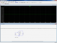
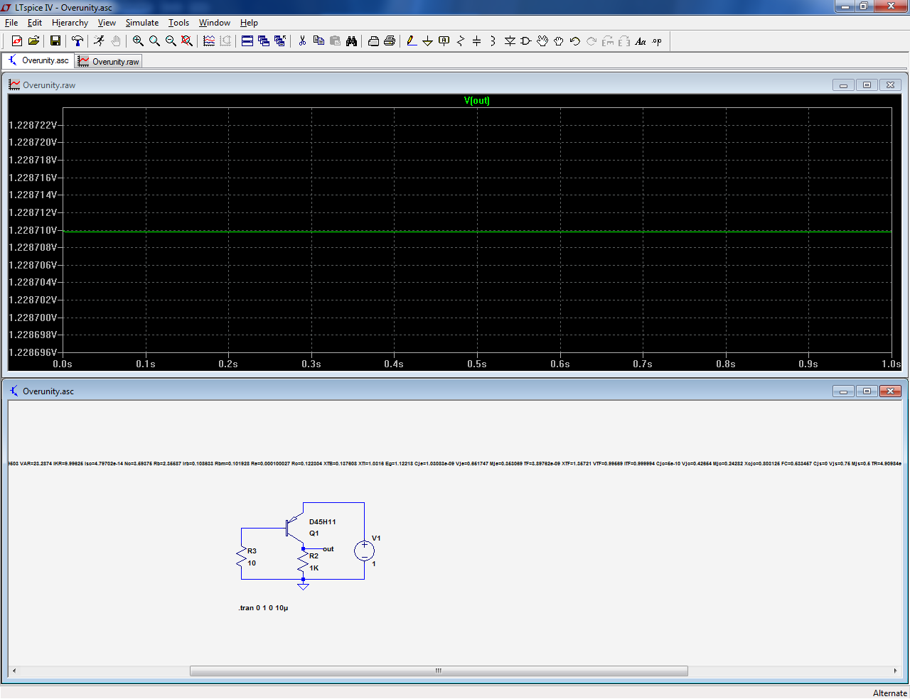
The D45H11 from ONsemi:

It manages a whopping 228mV excess!!!
Thus, beware if you simulate a design including this transistor: the results might be surprisingly optimistic!
Practically all of these models originate from Siemens: ~half of their models show it: BCP69B BCP51 BC638 BC369 2N2907 BCX69 BFP23 MPSA92, etc.
There is however one exception, and it is a particularly big one:
The D45H11 from ONsemi:
It manages a whopping 228mV excess!!!
Thus, beware if you simulate a design including this transistor: the results might be surprisingly optimistic!
Attachments
Hi Elvee,... There is however one exception, and it is a particularly big one:
The D45H11 from ONsemi:
It manages a whopping 228mV excess!!!
Thus, beware if you simulate a design including this transistor: the results might be surprisingly optimistic!
Attached is the D45H11 model (as Dd45H11 from TI). I get the same as you 228mV. Changing NF=NR=1 fixes it.
The plots show the saturation voltages as V(vcc,out) and V(vcc,out2). The second fixed model saturation voltage stays above zero as expected.
The active region is the first part (I<100uA). Notice changing NF=NR=1 does not affect this region much.
Alternatively, setting NR to match the original NF reduces the saturation voltage by 10mV (and is still above zero). Maybe this second fix would be the better (safer) option?
I notice most of the LTspice standard BJT models (at least in the LTspice IV) have NF=NR or within 0.1% of each other and NF never deviates from unity by more than a few percent should be free of this this saturation voltage model error.
The exception is the D45H11 in LTspice standard BJT library which is the only one with NF very different from NR. I haven't checked the LTspice XVII library.
We hardly ever need to model the reverse region for amplifiers. A zero cross detector (for speaker protection) is one application that uses the reverse model.
Attachments
...NF=NR=1 fixes it.
Thanks Ian for the pointer to the relevant parameters.
I did realize the reverse quadrant values have some effect on forward behavior but have never seen it so obvious and unrealistic.
As you stated, we rarely use reverse quadrant for audio and the parameters are often very suspect, plucked apparently at random.
So I often paid them little attention, from now on I will examine them more carefully.
Best wishes
David
Thanks for the insight. Mystery solved!Hi Elvee,
Attached is the D45H11 model (as Dd45H11 from TI). I get the same as you 228mV. Changing NF=NR=1 fixes it.
I had the curiosity of measuring a D45H11 from ONsemi in the same conditions as the sim, and although the result wasn't as spectacular (we should wait another 7~8 days for that), it was nevertheless rather unusual: the Vcesat was under 3mV, which is exceptional for a BJT.
I imagine that the bizarre spice parameter was a misguided attempt to reproduce this behavior.
Whoooo...3mV.Thanks for the insight. Mystery solved!
I had the curiosity of measuring a D45H11 from ONsemi in the same conditions as the sim, and although the result wasn't as spectacular (we should wait another 7~8 days for that), it was nevertheless rather unusual: the Vcesat was under 3mV, which is exceptional for a BJT.
I imagine that the bizarre spice parameter was a misguided attempt to reproduce this behavior.
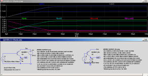
Please, have a look with collector and emitter switched.
Yes this looks crazy.. but this was done long ago to obtain very low Vsat. At the time of chopper amplifiers.
A BJT used this way, does work, npn becomes npn, so why not.
")
Perhaps this experience will prompt a bit of brainstorming upon the question: how much can I trust simulation results that use device models I did not create myself? And, what can I do to increase confidence in results if I am unable to create my own device models?
One possibility, which I use myself from time to time, is to swap in five or six different transistor part-types (device models) in a given position, and verify that the simulation results are not wildly dissimilar.
One possibility, which I use myself from time to time, is to swap in five or six different transistor part-types (device models) in a given position, and verify that the simulation results are not wildly dissimilar.
What you can do to check SPICE models is at least to measure some device characteristics, and compare these with the simulation results. I have not measured more than one or two device samples of any given product type due to the reason of spreads in parameters, as the tests, though straightforward, can be fairly lengthy doing them by hand.
For example, I recently measured a range of devices (2N3055, MJ2955, MJ29113/4, MJL3281A, BD139) and start with a Vbe:Ib:Ic plot. I use a 100M buffered amplifier on the base, which works quite well down to a few nA, though this is not often needed for audio. Then check output characteristics using a scope as a curve tracer (noting that some datasheets warn about taking measurements like this at Vceo (though I have only ever seen really bad results on RCA's epitaxial transistors where they "walk down", which are no longer made, I take it).
Junction capacitances can be measured at least for zero and reverse bias, to compare with the SPICE data, and the fT can be checked using a Class A bias circuit and squirting in a 1 MHz signal, to estimate fT, at least all to get first order checks done.
Inverse tests can be done to get reverse parameters.
I don't see an easier way of checking that the SPICE models aren't fake news. The tests I have done are part way to making SPICE models anyway. What I have not yet done is to check the temperature performance and tempco's.
Maybe it would be useful to recall that you are simulating circuit C which happens to include one or more instances of device D. How can you increase your confidence in the results of simulating circuit C? One way is to improve the modeling of device D (and all the other devices too). Are there additional ways besides "measuring and building device models myself"?
Swap-out may be one possibility. It has certainly helped me increase my confidence in simulation results, when I am forced to use device models I did not create myself.
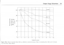
I expect, for example, that very few DIYA members possess test equipment which will allow them to measure beta droop of power BJTs via pulse methods (as the mfr datasheet uses).
_
Swap-out may be one possibility. It has certainly helped me increase my confidence in simulation results, when I am forced to use device models I did not create myself.
I expect, for example, that very few DIYA members possess test equipment which will allow them to measure beta droop of power BJTs via pulse methods (as the mfr datasheet uses).
_
Attachments
NF=NR mystery explained
I found an explanation as to why Nf should be equal to Nr in GP (Gummel-Poon) model which is the default for LTspice.
http://www.designers-guide.org/VBIC/documents/VbicText.pdf on p8 eq (17) shows Nf=Nr is required for energy conservation.
The equations given in this PDF are for the VBIC model which is an improved GP model, so it applies to the GP model as well. On p7 it explains that:
and concludes on p8:
and this recommendation applies to the earlier GP model as well since the VBIC use the same foundation equations as the GP.
As I noted in my earlier post LTspice standard BJT models has Nr to within a percent or so of Nf. One exception was the D45H11.
I notice the VBIC model is available in LTspice as Level=9 but I haven't used it yet. LTspice help on the VBIC model here Q Bipolar transistor - LTwiki-Wiki for LTspice
Has anyone used the VBIC model that would like to share a model or two with us so we can compare it with a GP model? Like the VBIC D45H11 model?
I found an explanation as to why Nf should be equal to Nr in GP (Gummel-Poon) model which is the default for LTspice.
http://www.designers-guide.org/VBIC/documents/VbicText.pdf on p8 eq (17) shows Nf=Nr is required for energy conservation.
The equations given in this PDF are for the VBIC model which is an improved GP model, so it applies to the GP model as well. On p7 it explains that:
"The ideality factors are introduced as parameters, rather being forced to be 1, to allow flexibility in modeling, to recognize that the theoretical analyses above are approximate, because non-ideal transport behavior is observed in HBTs, and for compatibility with the SGP model."
and concludes on p8:
"Therefore for silicon devices it is recommended that Nr=Nf be maintained for VBIC."
and this recommendation applies to the earlier GP model as well since the VBIC use the same foundation equations as the GP.
As I noted in my earlier post LTspice standard BJT models has Nr to within a percent or so of Nf. One exception was the D45H11.
I notice the VBIC model is available in LTspice as Level=9 but I haven't used it yet. LTspice help on the VBIC model here Q Bipolar transistor - LTwiki-Wiki for LTspice
Has anyone used the VBIC model that would like to share a model or two with us so we can compare it with a GP model? Like the VBIC D45H11 model?
Last edited:
...the question: how much can I trust simulation results that use device models I did not create myself? And, what can I do to increase confidence in results...
My method is to check the Spice model parameters for internal consistency and plausibility.
For instance, even if you don't measure the transistor, the VAF can be expected to be somewhere between 1 and 2 times the breakdown V (maybe a bit more for a transistor known for exceptional Early behavior, like the late, lamented Sanyo CRT units).
The VAR should be much lower, perhaps a tenth of VAF.
Similarly the relation between BF and BR.
RB and RBM need to be reasonable - sometimes an attempt to fit a curve will produce an RBM number of, say, 1E-3 but considered as a physical value of 1 milliohm then it is not plausible for the minimum base resistance of an audio transistor.
The RBM should be between 0.6 and 0.3 of RB.
And so on.
The final result should be at least physically reasonable and internally consistent.
Usually more reliable than a mindlessly fitted model.
That's why I was interested in Elvee's problem and Ian's work, now I have one more rule - NR = NF, or very close.
Best wishes
David
And more thanks to Ian for the link to the excellent paper, a nice find.
Last edited:
I don't think pulse hfe measurements would be too difficult to make, although I have measured D.C. values with the transistor mounted on a big hieatsink.
Pulse measurements would need a low mark:space ratio multivibrator and amplifier to drive the current; the base and collector currents can be measured using a scope, even single channel. Transient thermal time constants would permit something like 1ms on with 100ms off or longer being suitable. There would be several ways to pulse the transistor; either using a MOSFET perhaps in the emitter or just switching the base current with bipolars etc.
Pulse measurements would need a low mark:space ratio multivibrator and amplifier to drive the current; the base and collector currents can be measured using a scope, even single channel. Transient thermal time constants would permit something like 1ms on with 100ms off or longer being suitable. There would be several ways to pulse the transistor; either using a MOSFET perhaps in the emitter or just switching the base current with bipolars etc.
I found an explanation...
...to check for consistency from the model file.
I don't intend to write this as code but may write a text explanation.
Ian's excellent link has another equation that looks useful, (27) on p. 10.
CJE * VAR = CJC * VAF (Ae / Ac) = TF * IKF = TR * IKR
I am not sure about Ae or Ac, need to check the Spice parameters.
I think the other terms are direct maps to the Spice names.
Anyone have more information or more rules?
Best wishes
David
Last edited:
- Status
- This old topic is closed. If you want to reopen this topic, contact a moderator using the "Report Post" button.
- Home
- Amplifiers
- Solid State
- Overunity transistors