Disclaimer: this is a bit of a journey, do not try this at home, the HT on these amps stings like a wasp, your life is in danger and may end if you are not careful or don't know what you are doing.
I have a SA12 that I purchased of Ebay for about 150bux with both channels dead. I thought this might make a great project case for something or other I will think of in the future.
It arrived and quite a few components were blown including 3 of the 8 output devices. Capacitors were leaking although in spec, but the filtering caps and transformer are in good shape, even for 30years old.
After much discussion with Anatech (a mind of useful knowledge), and Grimberg (same mind of great knowledge), I came to the conclusion that successful ownership of an SA12 is down to the skill and willingness of the owner to experiment and take it wherever it may go due to unobtainium of some parts.
With this in mind, I set out and decided that the plan of action was as follows:
1- Recap (all but PSU)
2- Replace all semi's, as they are getting on in age, and not expensive to replace
3- Test various output MOSFETS to see what works.
Please note that I do not technically have the skillset for this whatsoever. I have been soldering and fixing small things since I was 9, but this is a bigger undertaking and would require significant research into how MOSFETS worked in general and what would be required to incorporate them into this design.
With all that being said, I set off and ordered some items from Mouser, including 20 each of IRFP240/9240, and at least 20 of each type of diode (i got through 19 Zeners.....).
Parts arrived and all electyrolytics and diodes were replaced. and the IRFP's matched using the NP method from First Watt. I aimed for discrepancies of no more than 1mv, which produced surprising numbers of pairs of each (which I would need as we will see later).
The keen observer would point out that the IRFP240 is not the same shape as the IRF130 which was OEM, and would be correct. THis is not going to be a pretty modification at all, which is depressing, but sadly part for the course.
Time of a pic, this is what the early experimental "prototype" looked like (it's messy I know, I will clean it up a little later on)
In the meantime I would also lose these horrid TO3 mounts.... arrrrgggghhh
At this point I should point out that I do this strictly for fun, I am not a professional and have had no formal training in any related field whatsoever.
I did purchase a few tools which made life much easier, so if you are thinking of following a similar path,. make sure you have a great soldering iron, a scope, a decent multimeter (not the crappy one you got free from Harbor Freight, buy an autoranging DMM, like a Fluke). and if you have some spare cash, a vacuum desoldering gun, like the one below, which really makes life much much easier.

One thing you will need is a device for bleeding the power supply (One of the reasons I used 19 Zeners in this project), this old fashioned incandescent light bulb does the trick
This is the Fluke in action, also check out the 4amp tripswitch-fuse replacement bottom left, this will save you lots and lots of money purchasing fuses which you will blow... alot
I did purchase a few tools which made life much easier, so if you are thinking of following a similar path,. make sure you have a great soldering iron, a scope, a decent multimeter (not the crappy one you got free from Harbor Freight, buy an autoranging DMM, like a Fluke). and if you have some spare cash, a vacuum desoldering gun, like the one below, which really makes life much much easier.
One thing you will need is a device for bleeding the power supply (One of the reasons I used 19 Zeners in this project), this old fashioned incandescent light bulb does the trick
This is the Fluke in action, also check out the 4amp tripswitch-fuse replacement bottom left, this will save you lots and lots of money purchasing fuses which you will blow... alot
Attachments
Last edited:
So anyhow, all diodes replaced, and IRFP's bolted to the heatsink (this needed smoothing out), I inserted the fuses in on one channel and turned the amp on. Surprisingly the magic smoke stayed in the box, and I only recorded about 300mv offset at the output. which was surprisingly low., and appeared to indicate that this concoction actually worked.
After a few minutes of stabilization I adjusted the offset to a range of -10 to around +20 mv, it never trully settles down and ranges over 30-40mv hot or cold.
I then measure various voltages and took notes, and low and behold the probes from the fluke touched and blew out 3 of the 4 IRFP's, and all 4 Zeners.... DOH, Now I know what those shrouds that came with the Fluke probes are for..... DONT TRY THIS AT HOME.
At least now I know that the jerry-rigged trip-fuses work as intended, and I did the right thing buying spares of all devices, better be more careful next time. A better look at the trip's
Off I go and replace the outputs with some of the other matched pairs, replaced the Zeners and the resistors, as they will need doing on the other channel, due to being scorched. The new results are much prettier, although to be honest, it is pretty hooky, and not far from the original design, as I cannot see a better way of doing it with this setup

Soldered on to the main PCB

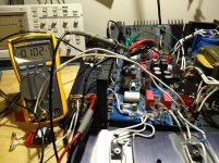
This time more care was taken and the testing was survived by all output devices and attached diodes. This is a pic of the Bias being adjusted to 100mv, which was the suggested number by Anatech. Note the dead fuse which was used to connect the 10A Ammeter function of the DMM (internal resistance below .05ohm).
As both the +ve and -ve rails are fused, you can also use the current draw to check how good your transistor matching was, in my case the NP method saw a differential of around 4mv between the two rails, which frankly with the lack of stability in this design is outside the measurable range IMHO (bias current seems to bounce around +-5-10ma).
OK so far so good, now rinse and repeat for the other side, reassemble and let's listen to it. With bias set on both channels to 100mv per rail the outputs get slightly warm, and are about 80deg off what a Krell would give off.
IMPORTANT, as I do not have a pair of burner speakers, I insert 1 amp fuses for the speakers, just in case things go South, this should protect my main living room assetts.
The sound straight "out of the box", with just being turned on is "interesting", great bass and mid's but the top end has the most severe case of MOSFET fizz and sibilance I have ever heard, even in the 80s this would have been wrong..
I discuss the issue with Anatech and he suggest increasing the bias a little and seeing where it goes. So I crank up the bias to 200ma per rail and wait for the transistors to stabilize after about 15 minutes listening sessions resume. Better but not "great".
I measure voltage drop on the power supply from 93.3v to around 91 with 200ma bias. I decide to increase bias to 300ma and measure a voltage drop to 88.3, which is excessive and not a recipe for a long life. BUT after the amp warms up the sound improves dramatically. It is up against a Audio Research Classsic 30, which is a brilliant little amp, and a great reference for the SA12 to beat (which it wont).
After walking away and leaving the amp running on the test bed over night, with 8ohm dummies and a fairly chunky 10v output sine wave, I listen again in the morning and it has really improved beyond anything I had hoped for.
I have since cranked up the bias to 330ma, and it now runs pretty hot, the outputs are barely touchable (about the same temp as a Krell ksa150), and the transformer is just a little cooler.
The sound is quite sublime, especially for a project that cost below 250bux. I have no worries about breaking stuff on this amp and will keep experimenting, I see various other MOSFETS in it's future as well as a much much bigger power supply, probably with a large external torroid, and a substantial CRCRC network. Of course the HT and heater supplies will need regulating at some point..... doh, this stuff is fun!
To anyone considering a similar journey, think long and hard, are you prepared to fail and lose the amp, are you prepared to electrocute yourself and die, will you do the necessary research before you open the lid and pull out a soldering iron?
Hi Konst,
I was really sorry to hear about your mishap. Ouch!
Yes, 330 mA is too high for the transformer especially. They are on the edge with an internal case temperature of 50 °C (normal for an original amp). I think the normal bias would be between 45 mV and 50 mV across a 0.1 R resistor in the fuse position. I also suspect that the bias network is close to packing it in. These are located between the fuses on the main board. The two capacitors are open by now, and if you flip the PCB over the resistors will be accessible. The two zener diodes are also pretty cooked. I changed that circuit entirely in the redesign.
While you're in there, replace the capacitors for the heater supply. They need it by now too.
These amps run stupid hot, and he recommended you leave them on all the time (don't!).
-Chris
I measured the temperatures this evening and the top of the case gets to around 39degC, the heatsinks range between 45degC and 49degC, the output devices at roughly 54degC and the transformer at 49degC after being on all day. This is at around 330ma per rail. At 200ma the heatsink drops to around 37degC and the FETs are at around 39-40.
I am not worried about the temperatures, they are pretty much in spec, but the transformer is making some mechanical noise, which reduces at 200ma. The rail voltage also drops to 87.3V from 93.3V without fuses, which is an excessive drop and in my opinion well outside the performance envelope. Dropping to 200ma brings the rail voltages back up to 89.5V which is acceptable.
It does however sound pretty good at 330ma, I think some beefing up of the power supply is called for, i now where did I put that 100va trafo hmmmmmmm?
There's clearly an error, here. If 330 mA is too high, then 450 mA (.045/0.1 = .45) is also. The service bulletin says 180 mA.Hi Konst,
I was really sorry to hear about your mishap. Ouch!
Yes, 330 mA is too high for the transformer especially. They are on the edge with an internal case temperature of 50 °C (normal for an original amp). I think the normal bias would be between 45 mV and 50 mV across a 0.1 R resistor in the fuse position. I also suspect that the bias network is close to packing it in. These are located between the fuses on the main board. The two capacitors are open by now, and if you flip the PCB over the resistors will be accessible. The two zener diodes are also pretty cooked. I changed that circuit entirely in the redesign.
While you're in there, replace the capacitors for the heater supply. They need it by now too.
These amps run stupid hot, and he recommended you leave them on all the time (don't!).
-Chris
Well, the original amplifier ran far too hot, period. Power transformers did fail as a result and I'm pretty sure that if one of these is in constant use (and survives), the filter caps are likely deteriorated badly by now.
Remember, the internal case temperature runs around 50 °C. I'm sorry, but that is simply too high to be reliable. In addition, they made their own transformers and did not provide the safety margins other manufacturers do. In other words, the transformers were substandard.
Remember, the internal case temperature runs around 50 °C. I'm sorry, but that is simply too high to be reliable. In addition, they made their own transformers and did not provide the safety margins other manufacturers do. In other words, the transformers were substandard.
I also fixed an SA220 in the same fashion, which has now been running for about 3 years every day, all day.
If you look at the service manual it suggests 280ma across a 1ohm resistor, which is updated with a later service bulletin (called "Hot-Rodding the SA-12") to 500ma. I found 500ma to be high, they run very hot, and I really don't think you need to punish the amp that much, something I know Anatech agrees with.
Hi there, I didnt measure it across a resistor, I inserted an ammeter instead of the resistor.Quick reply! But, do you mean that the bias should be 45-50 mA (45mV across 1 ohm, not .1 ohm), not 450-500 mA as your original post said?
If you look at the service manual it suggests 280ma across a 1ohm resistor, which is updated with a later service bulletin (called "Hot-Rodding the SA-12") to 500ma. I found 500ma to be high, they run very hot, and I really don't think you need to punish the amp that much, something I know Anatech agrees with.
Last edited:
I probably used the factory recommended value since that is so far back I can't remember. I use a clamp-on DC ammeter (HP 428), and also a 0R1 resistor mounted in a glass fuse body, or tacked across a blown fuse. This is easier for everyone else to do. You can load both channels and more quickly monitor between them. I use 0R1 to reduce voltage drop and get a more accurate setting.
I could tell you exactly if I looked up my manual, but I'm busy. I do know I use 0R1 resistors, none inductive types that are stable in value. I also use very good meters, HP 974A or a 34465A, I used to use 34401A meters.
Baking these amplifiers with high bias was necessary to get low distortion. He didn't use source resistors, so current sharing was down to the tight match between outputs (and I mean really tight!). The circuit gain is very low, so not much correction for distortion. That and the voltage amp had very non-linear feedback (yes, there is negative feedback). So what we have is a very poor design with poor execution. I've made changes that drop distortion and noise greatly with a more stable output section. Still sounds just like an SA-100 / 12 as well.
If you have to run very high bias to get distortion down, the design is poor.
-Chris
I was wondering if I should replace the bias and offset trimpots? If so, is the bias pot a multi-turn type? It seems so because I keep turning and turning and never seem to reach the end of travel.
I also notice that 100KΩ/1%/TC50 resistors were used in the bias and offset circuits. Is it necessary for drift?
I also notice that 100KΩ/1%/TC50 resistors were used in the bias and offset circuits. Is it necessary for drift?
A few possibly helpful hints here:
If you have one of these amps I recommend two things -
1. ADD SOURCE RESISTORS to the outputs, no matter which MOSFET you use, or emitter resistors if you go BJT. I don't know why Mr. Elliot had such as aversion to source resistors, but tightly-matched MOSFETS to not stay tightly matched forever.
2. Perhaps even more important: replace the 2.2uf (if I remember correctly)WIMA caps that couple the tube section to the output section. There is a design flaw when it comes to selecting these parts. The voltage rating seems adequate at first, but every time the amp is powered up, the full B+ voltage goes into that cap until the tubes warm up enough to conduct. (Yes, I measured it). This eventually punches enough holes in the cap that it starts leaking current, enough to eventually way over-bias the output section, not matter how much you try adjusting it. Eventually the outputs will fail.
- Home
- Amplifiers
- Solid State
- Counterpoint SA12, A journey