Not 0.22k.
the source resistors are 0r22
The two in series should measure 0r44
If you pass 100mAdc through that you will see a voltage drop of 44mVdc. Check the one that is not damaged to see what drop you get across each half.
You can use this method to check your source resistors and match them rather than just accept the standard 5%, or 10% tolerance.
Alternatively you can use 5 off 1r0 1% 600mW in parallel to get 0r2 3W
or 4off 1r0 in parallel with 1r8 to get almost exactly 0r22, but only 2.5W
what should i use to pass 100mA dc ?
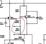
could i use bourns pots where R81 and R83 are ?The bias current is calculated from the volt drop across either of the 0.22 ohm resistors (always with no speaker attached).
The bias adjustment is done by what is called a vbe multiplier and altering the conduction of the transistor. The network of R81 and R83 would be replaced by a preset giving total control.
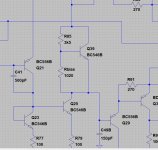
The numbers in the manual are so poor (blurred) that its difficult to quote which transistor it is. I think its Q39.
The trouble with fixed resistors are that you have no fine control and in fact very few amplifiers use fixed.
Here is the Cyrus redrawn and put into a simulation (it all works correctly) but I'm not 100% sure I've got all the reference numbers correct.
http://uk.farnell.com/bourns/3299w-1-251lf/trimmer-pot-250-ohm-10-25turn/dp/2329326could i use bourns pots where R81 and R83 are ?
for example ?
Assemble a two transistor Constant Current Source (CCS) using a To92 and a To220/247 with a couple of resistors.what should i use to pass 100mA dc ?
Use a DC supply of ~5Vdc to 9Vdc
Allow the CCS to warm up to a stable current and then quickly attach to your DUT resistors.
The preset needs to be either a 2k or a 2k2 type (2000 or 2200 ohm). Multiturn types are perhaps a bit excessive for this, a standard open type preset is the normal kind of fitment.
http://uk.farnell.com/bourns/3309p-1-202/trimmer-2k-9mm/dp/1689854
You will have to look at the board and decide for yourself which type will be the best physical fit, that means vertical or horizontal mounted multi turn or vertical or horizontal open standard types. You need to see how much room there is.
The preset will be wired using just two of the three legs, the middle and one end leg (either end, whichever gives the best fit). It will replace both series connected resistors which should give plenty of options for neatly mounting it.
Attachments
Not sure what Mooly means replacing both series connected resistors. Vbe multipliers should have the variable resistor in series with a fixed resistor to prevent too low a value appearing, and these compnents wired between the base and emitter of the Vbe multiplier transistor. The base-collector resistor should remain fixed. Reason being if an open circuit appeared in the potentiometer/variable resistor it would not cause the output stage to go bang.
Hi John,
The B-C resistor is fixed and meets the requirement of 'what if the pot went OC'.
Its a valid point you make on leaving a minimum value present at all times, my only practical concern is that it would be a little bit of an unknown to get the value right first time and yet still be able to set the bias correctly within the range of the preset.
When we get around to testing it will be with a bulb tester and with the preset initially set to maximum resistance to give minimum current.
A bit more on the fusibles. If you search Farnell for 'NFR' then it will bring up what they in stock. Not quite as expensive as I thought they might have been but only available in multiples of ten.
http://uk.farnell.com/vishay/nfr2500001000ja500/res-metal-film-fusible-100r-0/dp/9473890
http://www.vishay.com/docs/28737/nfr25.pdf
http://uk.farnell.com/vishay/nfr2500001000ja500/res-metal-film-fusible-100r-0/dp/9473890
http://www.vishay.com/docs/28737/nfr25.pdf
Thanks for the explanation, Mooly.
Tolerancing a circuit really needs the datasheet(s) to be examined for the transistor(s) being used. In this case the 2SC1775 is no help as it only gives Vbe(max). We could alternatively use worst case/best case device SPICE models, but often we are lucky to get just the typical.
Looking at a BC547 datasheet it gives 0.58-0.7V range with typical 0.66V - the old BC107 used to be 0.55-0.7 with 0.62 typical (at 2mA). Taking the range 0.58-0.75, and the required bias voltage range to be 3-4V (this is not a rigorous evaluation) the multiplier ratio needs to cover 4-7x. That makes the base resistor range 510 ohms - 1.2k. However, as the typical is around 810 ohms and the output triplet is likely to be sensitive to the setting (i.e. quite rapidly rising current with bias voltage) I'd keep the minimum resistance on the high side e.g. 620 ohms with a 1k pot, which now includes a 20% tolerance on the pot. That at least should err on the safe side, but without looking into the individual transistor characteristics and spreads, we still need a bit of precaution.
Hi folks i think i looked at fusibles but they all seemed to be in the states , the ones at the right tolerances anywayA bit more on the fusibles. If you search Farnell for 'NFR' then it will bring up what they in stock. Not quite as expensive as I thought they might have been but only available in multiples of ten.
http://uk.farnell.com/vishay/nfr2500001000ja500/res-metal-film-fusible-100r-0/dp/9473890
http://www.vishay.com/docs/28737/nfr25.pdf
that's absolutely brilliant thank youThe preset needs to be either a 2k or a 2k2 type (2000 or 2200 ohm). Multiturn types are perhaps a bit excessive for this, a standard open type preset is the normal kind of fitment.
http://uk.farnell.com/bourns/3309p-1-202/trimmer-2k-9mm/dp/1689854
You will have to look at the board and decide for yourself which type will be the best physical fit, that means vertical or horizontal mounted multi turn or vertical or horizontal open standard types. You need to see how much room there is.
The preset will be wired using just two of the three legs, the middle and one end leg (either end, whichever gives the best fit). It will replace both series connected resistors which should give plenty of options for neatly mounting it.
")
I wouldn't fret over the fusibles as I suspect they will be OK anyway when you measure them. Lets cross that bridge if the need arises.
What John is concerned about over the bias is that it would be good design to have the amp survive having the preset adjusted incorrectly, or turned from end to end with the amp on, and not for the amp to self destruct in the short term if that happens.
The real world problem is that bias is a critical adjustment where a small turn of the preset causes a relatively large increase in current flow and it would be difficult to give exact resistor values that would both safely limit the current and also guarantee that the preset gave a decent range of adjustment somewhere in the main part of its range.
So what we do is power the amp via the bulb tester initially. Thats the best safeguard of all for the first power on. Before that however we ensure the prest is turned to maximum resistance meaning that it appears as a 2k (or 2k) between B and E of the transistor. That forces a minimum bias state. We then very very slowly turn the preset while observing the voltage dropped across either of the 0.22 ohm resistors and confirm that it increases smoothly to say 20 millivolts. At that point the bulb may well start glowing a little, thats fine. When we are happy it all seems OK we turn the bias to minimum again and then for the final adjustment we perform it on full mains voltage. We look in the manual to see the recommended current... if its not given we will decide a suitable value based on the circuit configuration.
In my experience it is best to tag a couple of wires to the 0.22 ohm and connect the meter securely and permanently. That way there are no dithery fingers and bad connections and that allows 100% concentration on the setting of the preset.
What John is concerned about over the bias is that it would be good design to have the amp survive having the preset adjusted incorrectly, or turned from end to end with the amp on, and not for the amp to self destruct in the short term if that happens.
The real world problem is that bias is a critical adjustment where a small turn of the preset causes a relatively large increase in current flow and it would be difficult to give exact resistor values that would both safely limit the current and also guarantee that the preset gave a decent range of adjustment somewhere in the main part of its range.
So what we do is power the amp via the bulb tester initially. Thats the best safeguard of all for the first power on. Before that however we ensure the prest is turned to maximum resistance meaning that it appears as a 2k (or 2k) between B and E of the transistor. That forces a minimum bias state. We then very very slowly turn the preset while observing the voltage dropped across either of the 0.22 ohm resistors and confirm that it increases smoothly to say 20 millivolts. At that point the bulb may well start glowing a little, thats fine. When we are happy it all seems OK we turn the bias to minimum again and then for the final adjustment we perform it on full mains voltage. We look in the manual to see the recommended current... if its not given we will decide a suitable value based on the circuit configuration.
In my experience it is best to tag a couple of wires to the 0.22 ohm and connect the meter securely and permanently. That way there are no dithery fingers and bad connections
and that allows 100% concentration on the setting of the preset.sounds like a plan. the bits turned up from cpc today but I'll order presets too. thanks for giving the value of preset to get that saves me a lot of worry. I'll be pulling the outputs tomorrow (in wales in a battered campervan tonight). should i pull anything else off the board before i measure the fusible resistors, could anything else affect the measurements? i can remove each fusible individually if that's best ?I wouldn't fret over the fusibles as I suspect they will be OK anyway when you measure them. Lets cross that bridge if the need arises.
What John is concerned about over the bias is that it would be good design to have the amp survive having the preset adjusted incorrectly, or turned from end to end with the amp on, and not for the amp to self destruct in the short term if that happens.
The real world problem is that bias is a critical adjustment where a small turn of the preset causes a relatively large increase in current flow and it would be difficult to give exact resistor values that would both safely limit the current and also guarantee that the preset gave a decent range of adjustment somewhere in the main part of its range.
So what we do is power the amp via the bulb tester initially. Thats the best safeguard of all for the first power on. Before that however we ensure the prest is turned to maximum resistance meaning that it appears as a 2k (or 2k) between B and E of the transistor. That forces a minimum bias state. We then very very slowly turn the preset while observing the voltage dropped across either of the 0.22 ohm resistors and confirm that it increases smoothly to say 20 millivolts. At that point the bulb may well start glowing a little, thats fine. When we are happy it all seems OK we turn the bias to minimum again and then for the final adjustment we perform it on full mains voltage. We look in the manual to see the recommended current... if its not given we will decide a suitable value based on the circuit configuration.
In my experience it is best to tag a couple of wires to the 0.22 ohm and connect the meter securely and permanently. That way there are no dithery fingers and bad connections
This is what I would do:
1/ Remove the drivers, the outputs and the two 0.22 ohm resistors.
2/ The 100 ohm and 270 ohm fusibles wrapped around the drivers should now be checkable reliably in circuit, however the 100 ohm with a diode across it may give misleading results. If it does then just reverse the meter probes (to reverse the polarity of the meters own test voltage) and recheck. The remaining fusibles can be checked as well. Only if you can not get the correct reading having tried with the probes both each way should you remove one end of the resistor to check.
3/ While in this state do a quick check in circuit of the two 'pre drivers' that connect directly to the MJE243/244's. Just make sure they don't read low resistance or short between C and E. Red meter lead to C for the upper NPN and black lead to C for the lower PNP. Using the 'diode' range on your meter should give an open circuit result.
3/ Refit the new drivers, BD139 for the upper NPN and BD140 for the lower PNP.
4/ Refit the new outputs and ensure the tab of each (Collector) is correctly isolated from the heatsink. Use fresh thermal grease.
5/ Remove the two series bias setting resistors leaving just the 3k5 present between C and B.
At this point the amp could be tested with a bulb limiter. The bulb should be out, or at least dim. All the rails should be fairly near to normal and the DC voltage present at the amplifier output should be close to zero volts.
If that was OK then the bias preset can be fitted.
If the amp is difficult to work on then the preset can be fitted first. You are using two leads, the middle and either one of the end pins. When you have decided which pins, check the resistance between your chosen pins on the meter and make sure it reads the full 2k (2k2) of the preset by turning the control in the appropriate direction as needed. It MUST be at this initial value when fitted in place of those two resistors.
Thanks Mooly I'll get some time tomorrow to have a crack at this. got most of the bits but not the presets yet. Really appreciate the stel by step guide!This is what I would do:
1/ Remove the drivers, the outputs and the two 0.22 ohm resistors.
2/ The 100 ohm and 270 ohm fusibles wrapped around the drivers should now be checkable reliably in circuit, however the 100 ohm with a diode across it may give misleading results. If it does then just reverse the meter probes (to reverse the polarity of the meters own test voltage) and recheck. The remaining fusibles can be checked as well. Only if you can not get the correct reading having tried with the probes both each way should you remove one end of the resistor to check.
3/ While in this state do a quick check in circuit of the two 'pre drivers' that connect directly to the MJE243/244's. Just make sure they don't read low resistance or short between C and E. Red meter lead to C for the upper NPN and black lead to C for the lower PNP. Using the 'diode' range on your meter should give an open circuit result.
3/ Refit the new drivers, BD139 for the upper NPN and BD140 for the lower PNP.
4/ Refit the new outputs and ensure the tab of each (Collector) is correctly isolated from the heatsink. Use fresh thermal grease.
5/ Remove the two series bias setting resistors leaving just the 3k5 present between C and B.
At this point the amp could be tested with a bulb limiter. The bulb should be out, or at least dim. All the rails should be fairly near to normal and the DC voltage present at the amplifier output should be close to zero volts.
If that was OK then the bias preset can be fitted.
If the amp is difficult to work on then the preset can be fitted first. You are using two leads, the middle and either one of the end pins. When you have decided which pins, check the resistance between your chosen pins on the meter and make sure it reads the full 2k (2k2) of the preset by turning the control in the appropriate direction as needed. It MUST be at this initial value when fitted in place of those two resistors.
that's bloomin brilliant btw cheers !Thanks Mooly I'll get some time tomorrow to have a crack at this. got most of the bits but not the presets yet. Really appreciate the stel by step guide!
thank youIf I remember correctly this "C8837" is a factory number not the JIS.
You will need to get cross reference for which transistor they used.
A search suggests BUV28 for the outputs and MJE243 for the NPN driver MJE253 for the PNP driver.
Cheers,
I've gone for
MJE3055T x4 for the outputs and
BD139/140 for the drivers
going to mapling today to try to get presets for the bias as it's none adjustable on the issue 7 cyrus 1
- Home
- Amplifiers
- Solid State
- Cyrus 1 output transistor question. push-pull?