Of course with the removed silly 22nF input capacitor as you need
a fast risetime in Spice to excitate oscillation!
Don't forgett that in a real cirucit the thermal noise will excitate
your circuit from DC up to infrared and will trigger any instabilities...
And how exactly will thermal noise generate HF at the millivolt level that you're putting into the front end? input referred noise for this is likely to be better than 10nV/sqrtHz. There's just no way that is going to provide enough excitation.
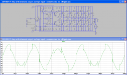
I have no idea why I'm even humouring you, given you're being incredibly rude and aggressive, but here's a version of the compensation (exactly the same amplifier) that'll put up with your square waves with no input HF filter, not to mention being reasonably stable down to around 6dB gain. There's a penalty for that though - 10KHz THD has blown out past my 1ppm design goal.
Attachments
It depends on what distortions are being generated.
An amp that has zero crossover distortion and ~0.1% of 2nd and 3rd THD will probably pass your test.
An amplifier that has crossover distortion and a very low proportion of 2nd & 3rd can sound terrible at the 0.1% level.
HF components of distortion from 5th to 25th that are very short term but high in amplitude will read low on a conventional THD meter. But it's the high amplitude (low duty cycle) that we can hear and dislike.
How does x-over dist differ from 2nd and 3rd order?
/
Great, you have finally added reasonable compensation caps ")
Your amp is now stable with about 20 degree of phase margin, though
on the border.
Try to add 10 nF to the output - it will again burst into oscillation.
No wonder, this beast has 107 dB open loop gain @ 10kHz!
And the open loop response does not look as if someone has
spend time on it.
Thermal noise is amplified as any signal,
and the output noise couple back to the input through the feedback resistors.
If the amp is unstable it will add in a positive way,
and in a few mS later you have an oscillator.
Besides the stability problem, the amp has other serious shortcomings:
It wastes 1/3 of the supply power with 4 Ohm load as the
diamond-buffers have serious shortcommings in power amps:
They limit the base current of the output transistors.
=> Bad peak power capability => forget them in this config.
The DC level of the first cascode stage is still rather random. It needs
a common mode stability circuit.
A current mirror would be a very good idea, but this does not work
in your amp.
The nice idea is that you have put 3 amplifier stages in one amp.
The bad news is that you have not though about it.
Look up some text about opamp design. The better ones have
three stages and some clever compensation schemes.
And forget your 1ppm goal. At this low levels simulation will tell
you exactly nothing as layout and transistor effects not modelled in
LTSpice are more important.
And how exactly will thermal noise generate HF at the millivolt level that you're putting into the front end? input referred noise for this is likely to be better than 10nV/sqrtHz. There's just no way that is going to provide enough excitation.
If i seem to rude, i apologize. At least i have spend my time to try to understand your beast.
I have no idea why I'm even humouring you, given you're being incredibly rude and aggressive, but here's a version of the compensation (exactly the same amplifier) that'll put up with your square waves with no input HF filter, not to mention being reasonably stable down to around 6dB gain. There's a penalty for that though - 10KHz THD has blown out past my 1ppm design goal.
Last edited:
I'm also playing with 3 sets of BD179/180 in lieu of the TIP41/42, simply because it allows me to spread the current source load across 3 transistors, and I can then use 2N3904/3906 rather than the BD139 there (higher gain), which in turn reduces current requirement for my reference.
Have you considered the BD139/40 -16 which are higher gain?
I consider part of the challenge being to keep it simple(r) simply because
increased complexity adds to build time and chances for error - in this case.
Also, I would not use off brand dirty cheap semis for fear of fakes, not sure
what you had in mind.
....d work just fine and you won’t hear the difference in the 1ppm THD vs 0.01%THD. These sound great (super bass punch and nice mods and highs). Also, they are single rail and can do up to 25w easy. They are the size of a large postage stamp and you can run them off cheap 19v smps.
35W TDA8932 Digital Amplifier Board Module Mono Low Power Stereo Amplifier | eBay
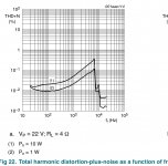
And the drop after 8khz - is that the measuring filter that is allowed for class D-amps i.e. in reality, the distorsion keeps increasing with freq?
//
Attachments
Last edited:

Member
Joined 2009
Paid Member
Great, you have finally added reasonable compensation caps
Your amp is now stable with about 20 degree of phase margin, though
on the border.
Try to add 10 nF to the output - it will again burst into oscillation.
No wonder, this beast has 107 dB open loop gain @ 10kHz!
And the open loop response does not look as if someone has
spend time on it.
Thermal noise is amplified as any signal,
and the output noise couple back to the input through the feedback resistors.
If the amp is unstable it will add in a positive way,
and .....
There’s good advice here, high feedback amps work great in Spice but need lotsa care in real builds. The promise of low distortion is hard to achieve but there are some good examples on the forum. Parasitic are critical and not included in basic Spice simulation. I’ve respun pcb’s before because of this.
I also agree with the futility of believing extreme low distortion from Spice. The device models are not that accurate, passive portrayal often idealized. Spice is helpful to explore changes, tolerances, doing some sensitivity analysis on key parts parameters.
My best amp simulates with low distortion, I aim for <.005% but I have also enjoyed amps with higher distortion and I will continue to build different types.
Last edited:
Oh dear. Now I just have to get a move on with the line arrays.
Given that this is a ground up design, is there any advantage in making a higher voltage amplifier to drive more than one TC9 in series?
Graham.
It is better to drive them in parallel since lower load impedance requires lower
rail voltages keeping the outputs out of secondary breakdown.
And the drop after 8khz - is that the measuring filter that is allowed for class D-amps i.e. in reality, the distorsion keeps increasing with freq?
//
They probably only show data out to 8kHz because distortion is predominantly 2nd and 3rd harmonic, so 8kHz x 3 is 24khz and data acquisition may only be 48khz.
The amp I linked is a mono PBTL setup where both channels drive one load. The current would be half, so I think distortion is less than plot which is for BTL stereo load.
I should measure it driving 8ohm load to 10w for grins.
It seems all the people suggesting the use of "cheap car audio chps" did not notice the THD target of <1ppm.
As one who suggested those, I most certainly did notice the <1ppm distortion target but that's just a simulation target (as udok and Bigun have noted already). Which experienced LTSpicers know bears little connection to the distortion measured from a prototype at such insignificant low levels.
Hi xrk971,
Please keep material like that linked to the discussion, in this case at least the same topology as the thread was very specific about the design.
-Chris
Sorry about that - I do think it is appropriate to discuss whether or not two dozen transistors are needed for low distortion though.
It’d be a neat trick if I could manage 100dB of OLG at 10KHz.
Why not to draw open-loop gain plot?
Do you need help with this?
And maybe you could agree with a hair under 10W at 8 Ohm with one LT1210.

That’s over your budget, but diamond output no so good as 2EF for such a load.
Also i’ll think about cheap as dirt NE5532 with 2EF output buffer.
An ideal amplifer behaves like a R-C filter (with a constant gain facdtor)
with exactly NO ringing. This is independent of HF excitation at the input!
No. Not any.
This is true for dominant pole correction one-pole compensation approach.
For high-order correction there are a huge math must be solved for having aperiodic step response without input filter.
Usually an amp itself are compensated for having formal stability margins. Then input filter with corner freq two orders lower than UGF applied at the input.
Voila - aperiodic step response at any excitation.
But designing an high-order compensated amp core with aperiodic step response is not a trivial task at all.
Valid point, but not in this thread where the design is clearly laid out. If you don't agree with the subject, post in a different thread.
-Chris
Ok, if you want, feel free to remove my posts - sorry for being OT.
Hi,
Thanks in advance,
Matthias
can you please give a pointer to such a derivation? No problem, if it is on the mathematical side.For high-order correction there are a huge math must be solved for having aperiodic step response without input filter.
Thanks in advance,
Matthias
Last edited:
Have you considered the BD139/40 -16 which are higher gain?
I consider part of the challenge being to keep it simple(r) simply because
increased complexity adds to build time and chances for error - in this case.
Also, I would not use off brand dirty cheap semis for fear of fakes, not sure
what you had in mind.
I've not found a model for the -16 BD139/140s. What does work reasonably well is just throwing a pair of 2N3904/3906 transistors in parallel - at 20mA bias they'll be dissipating 180mW each, as they should share current very well, hot but manageable.
Everything is based on what I can buy at Mouser or Digikey, so On Semi, Fairchild etc parts.
Hi,
can you please give a pointer to such a derivation? No problem, if it is on the mathematical side.
Thanks in advance,
Matthias
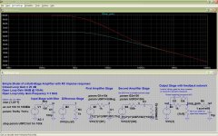
Assume you have two amplifier stages:
A simple and workable approch is that the second stage gain
goes down to unity at a frequency at least 10 times less than the
open loop unity gain frequency of the first stage.
E.g. first stage has open loop UGF of 3 MHz,
and second stage has UGF of 300Khz.
The overshoot will not be more than 4% in this case,
and only with fast impulses which do not occur in Audio.
If you design your amp this way, it will behave like a R-C filter with gain defined by your feedback resistors.
I added a LTSpice file to illustrate this concept.
I choose a UGF of 3 Mhz for the whole amp, maybe even 3 MHz is too much for a TIP41/TIP42?
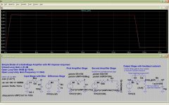
If the second amplifier has a UGF of more than 1/10 of the UGF of the
whole amplifier, you could use a bessel or butterworth filter,
but this must be tailored to so that the frequency response of the
whole amp is a bessel filter.
I could not think of a better method than trial and error.
Maybe BesPav can help us?
@ Suzie: I apologize for my posting style. It was not my day.
Attachments
Last edited:
Have you considered the BD139/40 -16 which are higher gain?
Sure? IIRC a designation without suffix covers the whole hFE range, i.e. a transistor without suffix can have a beta between the lowest and the highest value given in the datasheet. Suffixes like -16, -25 and -40 index the individual transistor to one of three groups (with large overlappings, btw.), of whose -16 means the lowest beta values.
Same as A, B and C in small signal transistors.
Never seen any BD139 or 140 of recent make to be grouped, hence probably the absence of groups in the sheets.
Best regards!
- Home
- Amplifiers
- Solid State
- Cascading diamond buffers - a cheap low THD 10W amp with TIP41C