Hello,
I would like to convert car amplifier into home amplifier!
I opened it up found that power supply pcb and amplifier pcb are seperated.
From power supply it goes -27v gnd +27v.
The amp is oldschool Car technic 1000w, 4channel amp and I can`t find any good info of it on the internet.
It has 4x D718 transistor and
4x B688 transistor.
That means 1x D718 and 1x B688 per channel, what power can this make at -27v-0+27v?
Now about the power supply:
It has 2 x 25A fuses
50A (because of 2 * 25A fuses) x 14,4v (operating voltage) = 720w
So I will need 720va center tapped transformer and
720va / (27v*2) = 13,3A... so 15A diode bridge.
Now how do I design the supply?
I know that voltage will rise when converted to dc and because of capacitors, so I don`t know how much voltage do I need at transformer rails and what kind of capacitors do i need?
Thank you for help")
I would like to convert car amplifier into home amplifier!
I opened it up found that power supply pcb and amplifier pcb are seperated.
From power supply it goes -27v gnd +27v.
The amp is oldschool Car technic 1000w, 4channel amp and I can`t find any good info of it on the internet.
It has 4x D718 transistor and
4x B688 transistor.
That means 1x D718 and 1x B688 per channel, what power can this make at -27v-0+27v?
Now about the power supply:
It has 2 x 25A fuses
50A (because of 2 * 25A fuses) x 14,4v (operating voltage) = 720w
So I will need 720va center tapped transformer and
720va / (27v*2) = 13,3A... so 15A diode bridge.
Now how do I design the supply?
I know that voltage will rise when converted to dc and because of capacitors, so I don`t know how much voltage do I need at transformer rails and what kind of capacitors do i need?
Thank you for help
Power supply design is okay except you better put DC detect and shutdown if the rail fuse blows. One blown fuse means 40 v dc on the speaker and a cone with ripped suspension or a shorted turn probably.
Car amps after a certain date were made for 1 ohm speakers, which in general, and IMHO, don't sound very good.
Wattage, the transistor numbers don't mean anything, but the package size does. 1 pair TO247/263 maybe about 40 W 2 ohms, 1 pair TO220 maybe 25 W 2 ohms. The first are about 13 mm wide the second about 8.
Power supply design is okay except you better put DC detect and shutdown if the rail fuse blows. One blown fuse means 40 v dc on the speaker and a cone with ripped suspension or a shorted turn probably.
Car amps after a certain date were made for 1 ohm speakers, which in general, and IMHO, don't sound very good.
Wattage, the transistor numbers don't mean anything, but the package size does. 1 pair TO247/263 maybe about 40 W 2 ohms, 1 pair TO220 maybe 25 W 2 ohms. The first are about 13 mm wide the second about 8.
Hy thank you for you time.
I can overcome the problem by putting fuse between the mains and primary instead on dc rails.
Can you tell me about year from when car amps were made for 1ohm? I have vintage Pioneer car amp 2 x 60w from 1988 that sounds good driving 2 4ohm drivers. I also have renegade ren1100s and it sounds good to me connected to my Pioneer CS770 speakers.
I think that this amp that I want to convert is from mid-late 90s.
I don't recall to see car amp's be able to drive 1ohm stable, except monoblocks and few other ones. 2ohm usualy.
I'm mainly listening to electronic music so high power means more to me than superior quality.
I'm not a car amp expert. I just know what speakers I pick up on the curb are. Trending down in ohms and trending towards rubber in the diaphragm. Late speakers I just use the magnet to sweep the drive for screws. I thought the whole idea of hi fidelity went in the trash when car systems were dominating the stores. The "listening room" at Circuit City was a zoo full of noise. CD's started being mastered for maximum punch on the roadway, not to sound like any kind of musical instruments.
1 ohm capable car amps will drive 4 ohm speakers, just not as much power transfer. +-40 v rails gets you into 2 digit wattage anyway on 4 ohms.
20 years ago I'd have suggested using a car battery charger to power the original power supply, but new chargers are so **** computer controlled they are likely to shut down at the stupidest times. Cheaper to buy a naked transformer & bridge, now, and distributors now take debit cards, which means you don't need to make a long distance call to estimate the freight charge.
Last edited:
Look it up 2sd718, it is a 80W bjt in a TO-3P. A pair of them would give about 40-50W /ch into 8 ohms and that is about it. 50x4=200W, a 250-300VA trans would work.
27Vpk*0.7071=19Vrms into 8 ohms is (19x19)/8)=~45W
Also have to take in account voltage sag under load
A 60VCT transformer is too much V, more like a 40VCT (20V*1.414) = 28.3Vpk
27Vpk*0.7071=19Vrms into 8 ohms is (19x19)/8)=~45W
Also have to take in account voltage sag under load
A 60VCT transformer is too much V, more like a 40VCT (20V*1.414) = 28.3Vpk
Last edited:
Any bridgeable car amp will be 2 ohm capable. As an example of one of the "cheater" amps from the 90's was a high end USAmps that had a rather low power rating into 4 ohms,something like 60 watts bridged ,but, was capable of 250 watts into 1 ohm bridged. This amp also had 10 outputs and 4 drivers per channel as well as 6 switching transistors for the power supply and a transformer wound with 8 gauge wire on the secondaries. When you see the inside of an amp made for low impedance you will know there is a difference. Most of these types of amps were manufactured during the 90's when car audio competition was a big thing.
As far as powering car amps in home a basic 300 watt atx pc supply works well and are inexpensive these days. Look on youtube for videos on converting pc supply into a bench supply. I would not alter the amplifier myself, most car amps have far better protection circuits than most any home audio equipment does. If you do go the transformer route I would measure the actual rail voltages in the amp before choosing one. You also won't need a bridge rectifier as the ones already in the amp will work fine. All you need to do is desolder and lift the secondaries of the original toroid that is in there and connect the secondaries of the new transformer there, however, I don't know if the double fuses would imply 2 supplies, one for each stereo pair.
As far as powering car amps in home a basic 300 watt atx pc supply works well and are inexpensive these days. Look on youtube for videos on converting pc supply into a bench supply. I would not alter the amplifier myself, most car amps have far better protection circuits than most any home audio equipment does. If you do go the transformer route I would measure the actual rail voltages in the amp before choosing one. You also won't need a bridge rectifier as the ones already in the amp will work fine. All you need to do is desolder and lift the secondaries of the original toroid that is in there and connect the secondaries of the new transformer there, however, I don't know if the double fuses would imply 2 supplies, one for each stereo pair.
I'm not a car amp expert. I just know what speakers I pick up on the curb are. Trending down in ohms and trending towards rubber in the diaphragm. Late speakers I just use the magnet to sweep the drive for screws. I thought the whole idea of hi fidelity went in the trash when car systems were dominating the stores. The "listening room" at Circuit City was a zoo full of noise. CD's started being mastered for maximum punch on the roadway, not to sound like any kind of musical instruments.
1 ohm capable car amps will drive 4 ohm speakers, just not as much power transfer. +-40 v rails gets you into 2 digit wattage anyway on 4 ohms.
20 years ago I'd have suggested using a car battery charger to power the original power supply, but new chargers are so **** computer controlled they are likely to shut down at the stupidest times. Cheaper to buy a naked transformer & bridge, now, and distributors now take debit cards, which means you don't need to make a long distance call to estimate the freight charge.
Thank you for explanation. I could say that I`m aware of the quality, but I like big bang, high volume, I always turn bass boost on as high as I can without getting music distorted
I didn`t get that +-40 rails part, because of my lack of understanding english language... Are you saying that I should check or replace some components to handle 40v and use +-40v power supply?
Any bridgeable car amp will be 2 ohm capable. As an example of one of the "cheater" amps from the 90's was a high end USAmps that had a rather low power rating into 4 ohms,something like 60 watts bridged ,but, was capable of 250 watts into 1 ohm bridged. This amp also had 10 outputs and 4 drivers per channel as well as 6 switching transistors for the power supply and a transformer wound with 8 gauge wire on the secondaries. When you see the inside of an amp made for low impedance you will know there is a difference. Most of these types of amps were manufactured during the 90's when car audio competition was a big thing.
As far as powering car amps in home a basic 300 watt atx pc supply works well and are inexpensive these days. Look on youtube for videos on converting pc supply into a bench supply. I would not alter the amplifier myself, most car amps have far better protection circuits than most any home audio equipment does. If you do go the transformer route I would measure the actual rail voltages in the amp before choosing one. You also won't need a bridge rectifier as the ones already in the amp will work fine. All you need to do is desolder and lift the secondaries of the original toroid that is in there and connect the secondaries of the new transformer there, however, I don't know if the double fuses would imply 2 supplies, one for each stereo pair.
Hello,
thank you for explanation. Are we talking about RMS or Peak power?
I`m aware of option of using PC PSU, as I had this setup in the past powering my 500w JBL at home.
I also don`t like the idea in term of efficiency. Because you get power losses when stepping down from 220v to 12v and again when boosting from 12v to +-27v.
This time I wan`t to make something more professional. The idea of lifting transformer secondaries and connecting secondaries of new transformer is good idea
That way I don`t need to build new power supply circuit and discard amp`s protection circuit.Can I measure voltage at secondaries with them connected or do I need to disconect them and then measure?
Thank you
Look it up 2sd718, it is a 80W bjt in a TO-3P. A pair of them would give about 40-50W /ch into 8 ohms and that is about it. 50x4=200W, a 250-300VA trans would work.
27Vpk*0.7071=19Vrms into 8 ohms is (19x19)/8)=~45W
Also have to take in account voltage sag under load
A 60VCT transformer is too much V, more like a 40VCT (20V*1.414) = 28.3Vpk
Hello, I made the decision that I will use the amps power supply, I will just lift secondaries of it`s transformer and connect secondaries of new transformer to it as jerluwoo suggested.
"Look it up 2sd718, it is a 80W bjt in a TO-3P. A pair of them would give about 40-50W /ch into 8 ohms and that is about it. 50x4=200W" is this RMS or peak power?
Thank you
So this is what I measured:
55-0-55 from secondaries
-55 and +55 at diodes
-27 and +27 DC coming from diodes... is this normal?
-27 and +27 (27-0-27) at rails going to amp section

Voltages was measured at idle.
If this is correct (55VAC to diode 27VDC from diode) that means that I need 55-0-55 300VA (as rsavas suggested) transformer ?
Thank you
55-0-55 from secondaries
-55 and +55 at diodes
-27 and +27 DC coming from diodes... is this normal?
-27 and +27 (27-0-27) at rails going to amp section
Voltages was measured at idle.
If this is correct (55VAC to diode 27VDC from diode) that means that I need 55-0-55 300VA (as rsavas suggested) transformer ?
Thank you
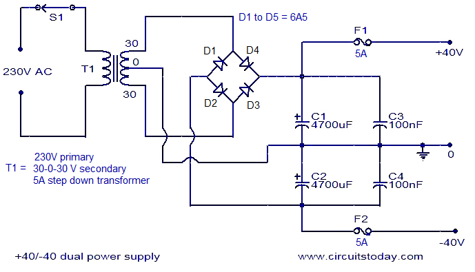
The diagram post two showed +-40 v rails. So that's what I talked about.
The 55 VAC versus +-27 is a bit odd. I think they are splitting the AC into +- by deriving a center speaker ground somehow where you didn't measure. Either it is a center tap transformer and your missing the center tap point, or something. Center tap transformers often don't use bridge rectifiers, but single diodes.
So you want +-27 v rails at idle. Transformers are sold by the average voltage, not the peak voltage. (Average * 1.4)-1.4v = peak. The 1.4 v is the two diode drops of the bridge. So to produce +-26.5 you need a 20 v transformer with two windings, the two tied together make the center speaker ground. Toroids come that way. Expensive (now) E-frame transformers tend to have one winding and a center tap.
Confirm your 27 v reading by looking at the rating on the rail caps (the 4700 in diagram post 2. Should be 10-40% higher than that. BTW on an amp this old, the rail caps probably need replacing. I alway do after 20-30 years.
4 pairs output transistor for two channels is about 160 W so a 300 VA transformer would be adequate. Extra VA won't hurt the amp, too low a speaker resistance does. That's average or RMS power, but electronic or house music doesn't have much of a crest factor, so don't count on a big music power surge like I get on 1812 overture cannon shot.
Whether it can sustain 160 W/ch depends on how big the heat sinks are and how good the fan is.
If your rail caps are rated higher than 35 v maybe you can up the transformer to a two 24 v winding transformer which would be easier to find in stock.
Depends on your speaker. A 2 ohm speaker, 27 v rails is good, but with an 8 ohm speaker, four 2sd718 could be capable of 160 w/ch with 55 v rails. You could drive them with an op amp, see the op amp + pass transistor threads on chip amp.
I could laugh at phase; Slovenia is 4000 miles and a customs barrier from Seattle. I get junk receivers for $10 but they are chock full of electrolytic caps that need replacing, dozens of them, even down to 0.47 uf. Better a junk Peavey PV-4c for $40 + 30 freight; at least the heat sinks, case, fan are real. The driver boards could be scrapped & some IC design put in.
Look at the honeybadger boards under diyaudiostore up top. They are pretty powerful: 2sa1943/sc5200 outputs should be common in Europe. A 400 va transformer would be more suitable for that. Buy your transistors from the store with the boards or from an authorized distibutor like farnell or RS or that german one, reiser?: lots of counterfeits on the resale market.
Last edited:
The CS800s is no compromise; listening to it now @ 1.5 W/ch.I’m glad you like your Peavey amp!
The PV-1.3k is a bit industrial at low volume, but really projects down the whole street when I play 1812 overture & Sousa marches on 4th of July. PV-xx don't hum, have great transformer screening. Great air flow, fan control (in the 1.3k), adequate heatsinks, case is roadworthy. The PV-xx compromises were in the circuits, designed for only high volume, and not adequately protected against shorted phone plugs to the speaker.
Last edited:
- Status
- This old topic is closed. If you want to reopen this topic, contact a moderator using the "Report Post" button.
- Home
- Amplifiers
- Solid State
- Converting car amplifier into home amp