I understand nothing in these parameters, just copied them. They were published by Roender in FC100 thread. Aren't they correct?
I recommend sticking with the .models in simulation 4 which have been tested by trusted sources besides these have worked in the development of the circuit to the present stage and they won't need editing.
If you want to use BC550C and BC560C add the following SPICE directive to your simulation ".inc http://www.cordellaudio.com/book/Cordell-Models.txt"
re-draw
Re-drawing for clarity reveals a couple things. C9,C10,C11,C12 are counter productive and only serve to couple supply noise into the signal path. Of course simulation using "perfect voltages" will not show a problem. R8 and R9 have been super tweaked to cover a poor bias design that is super sensitive to tolerance. Probably the best solution is to scrap the DC feedback gain since the input is not DC coupled anyway, ie put large caps in series with R2, R4. This amp lacks output protection, etc, etc.
Re-drawing for clarity reveals a couple things. C9,C10,C11,C12 are counter productive and only serve to couple supply noise into the signal path. Of course simulation using "perfect voltages" will not show a problem. R8 and R9 have been super tweaked to cover a poor bias design that is super sensitive to tolerance. Probably the best solution is to scrap the DC feedback gain since the input is not DC coupled anyway, ie put large caps in series with R2, R4. This amp lacks output protection, etc, etc.
Attachments
Hi AndriyOL,Does anybody know why the sim isn't working?
Can we use A1312, C3324 PSpice models in LTSpice? They supposed to be the same as A970, C2240.
Your Sim 5 circuit is now working with A1312, C3324 for the Vbe multiplier.
Compensation adjusted for about 60 deg PM.
I copied the original models from sim4 since they seemed to be corrupted. I edited 2SA1360 to 2SA1360_k, etc. The k signifies keantoken versions, I think.
I used inbuilt BC547C & BC557C models as equivalents to BC550C & BC560C. You can get BC550C & BC560C from Bob Cordell's library if you want to be more precise. I think the BC550C & BC560C are lower noise versions.
Cheers
Attachments
Re-drawing for clarity reveals a couple things. C9,C10,C11,C12 are counter productive and only serve to couple supply noise into the signal path.
If I remember correctly, C9, C10 were recommended to suppress rf ingress if Q16, Q17 base traces exceeds 3-4cm on pcb. Don't know about C11, C12.
Hi AndriyOL,
Your Sim 5 circuit is now working with A1312, C3324 for the Vbe multiplier.
Compensation adjusted for about 60 deg PM.
Thanks Ian.
Actualy I used BCs in IPS as they can show more closer to reality results. However if we can use A1312, C3324 now which are beleived the same as A970, C2240 used on my pcb, I'll substitude the BCs to them. They aren't fit well for Vbe multipler due to not have best hfe value, better alternative could be C3326 or 2SC4495 as Max commented. Btw, they don't have a complementary pair if such have to be used in vbe multiplier circiut.
Shall we use Hagermann vbe doubler instead current vbe multiplier?
Last edited:
cross coupling
C13 is in parallel with C19 and they could be replaced with one small cap. 100n (C13) may be enough. C14, C19, C20 are cross coupling caps which couple the opposite polarity drive so that especially the larger slower transistors do not float on when driven fast (aka "shoot-through"). I would swap C19 and C20 but R21 is only 12 Ohms so that is another way to pull power transistors off fast. Only 12 Ohms at R21 is going to get Q19 and Q18 a bit warm because that will require about 100mA or 4.5 Watts each, and 80 Ohms at R22 and R23 will call for about 0.4 Watts in Q21 and Q22.
There are a lot of "unconventional" bits here and we want to think long about what is a good idea and what causes issues. I would spend some time making the front end bias more predictable. This is always a problem with totally symmetric designs. Symmetry reduces 2nd order distortion but many amplifiers deliberately exaggerate 2nd order distortion because it sounds very musical, and it's the secret sauce in many guitar amps and the "Aphex aural enhancer".
Without C19 THD doubles. Perhaps it can be reduced in size to 50-100uF without any change in sim.
R21 12 Ohms value have the lowest distortion and a little bit contribute to stability, but can be swapped for 16 Ohms without any harm I think. I chose R22, R23 80 Ohms as optimal value in stability\THD balance for current CFP output set.
Redesinging input stage for more predictable bias considering simplisity and outcome of current circuit isn't reasonable I think. As I have tried in real built, it's possible to set the DC offset not more than +-10mV without too much efforts. Alternative option could be to swap for more complex and robust CCS, which was mentioned a couple of pages back.
Can a triple output stage with a CFP diver be made non-switching?
I just found Valery's (vzaichenko) 2015 amp "VERTICAL front-end + Non-Switching OPS with Class A driver stage" Post 144 (p15) Revisiting some old ideas from 1970's - IPS, OPS see Valery's attachment "...ops-101-sch.jpg".
It might be useful for RET Darlington and triple Darlington output stages that are used in our amps. I thought there must be a simple way to do it .
.
But a CFP diver of a triple output stage like used in this thread it can't be easily applied to the driver like Valery does since the Loconthi-T resistor (R21 in AndriyOL's) for the output transistors will still turn off the other power transistor with enough output voltage.
One way with a CFP driver is to add diodes to the base resistor feed node of the power transistors after the "T" resistor. But this won't allow fast charge removal of the power transistors unless extra charge removal transistors are added. It seems at least to me that there isn't any simple modifications for a triple output stage using a CFP driver to make it non-switching. Any ideas?
Cheers
@All,...Does anyone know of a simple add-on to make the standard Lin topology (or CFA) output transistors stay slightly on (about 30mA is enough) to keep the FT high? It might help the PM.
I just found Valery's (vzaichenko) 2015 amp "VERTICAL front-end + Non-Switching OPS with Class A driver stage" Post 144 (p15) Revisiting some old ideas from 1970's - IPS, OPS see Valery's attachment "...ops-101-sch.jpg".
Non-switching OPS uses a bias clamping technology, similar to what Technics used in 80-90's integrated as well as power amps - the 2-nd spreader sets the bearing voltage for a diode clamp, maintaining the minimal current through the output devices when they are not in use. Simple, but rather efficient.
It might be useful for RET Darlington and triple Darlington output stages that are used in our amps. I thought there must be a simple way to do it
.But a CFP diver of a triple output stage like used in this thread it can't be easily applied to the driver like Valery does since the Loconthi-T resistor (R21 in AndriyOL's) for the output transistors will still turn off the other power transistor with enough output voltage.
One way with a CFP driver is to add diodes to the base resistor feed node of the power transistors after the "T" resistor. But this won't allow fast charge removal of the power transistors unless extra charge removal transistors are added. It seems at least to me that there isn't any simple modifications for a triple output stage using a CFP driver to make it non-switching. Any ideas?
Cheers
As many know, there is static crossover distortion (static XOD) and dynamic crossover distortion (dynamic XOD). Static XOD results from variations in the total transconductance of the output stage as the output current passes through zero. It is the most commonly understood form of crossover distortion, and is often understood by seeing a wingspread plot of output stage gain as a function of output voltage (or current) into a load. Static XOD is essentially frequency independent, but it is usually manifested as an increase in total closed-loop amplifier distortion as frequency increases due to global negative feedback falling with frequency. When we bias an output stage to the Oliver criteria, theoretically putting 26 mV across each emitter resistor, we are seeking to minimize static XOD.
Dynamic XOD is a different beast, and it is important not to confuse it or its symptoms with static XOD. Dynamic XOD is related to turning the output transistors on and off sufficiently fast as output current changes rapidly at high frequencies when the output current passes through zero. It is also called switching distortion. It mainly has to do with the rate of change of output current, or current slew rate. The most significant source of dynamic XOD or switching distortion is the inability to switch off quickly an output transistor that has been conducting a large amount of current. This results from not enough ability to suck out minority carriers from the base. In most output stage arrangements, turning the output transistor on sufficiently fast is much less of a problem. The most straightforward and effective way to reduce dynamic (switch-off) XOD is to be able to provide a sufficiently high pull-out current from the base of the output transistor. The required amount of current is proportional to the output current slew rate and inversely proportional to the ft of the output device. In a Locanthi Triple, for example, running the driver transistors with a high bias current, on the order of 30-60 mA or more, largely solves this problem. In simulation, look at the collector current of the driver transistor under conditions of high output current swing at high frequencies (e.g., full power into a 4-ohm or 2-ohm load at frequencies of at least 20 kHz). It should never go to zero. If it goes to zero, the driver has lost control of the output transistor.
So-called non-switching output stages, briefly the rage in the late 70's through the mid 80's, were supposed to address dynamic XOD, but most did not. Nor did most benefit static XOD. They all attempted by some means to keep a minimum amount of current flowing in the output transistor at all times. With almost all of them, the transconductance of the "off" transistor still went to zero, even though the transistor was still conducting some roughly fixed amount of current. Transconductance contribution is what counts in regard to static XOD, so these approaches did nothing to minimize static XOD.
Keeping the transistor on also really did little to reduce switching distortion as well. That is because the real issue with dynamic XOD is the ability to turn the transistor on and off with adequate speed. Although keeping a minimum amount of current probably softened and smoothed the switch-off a bit, it did not, by itself, address the core problem of being able to pull out minority carriers quickly enough during fast switch-off when there was a high output current slew rate.
In an output stage where the drivers are able to supply plenty of turn-on and turn-off current under high output current slew rate conditions, I have never seen a simulation where circuitry to keep a minimum amount of current flowing in the output transistors during their off time really made any difference.
Circuits that gradually reduce transconductance contribution of the transistor turning off can improve matters somewhat, but most of the non-switching designs did not do that. Many were very misleadingly given names that implied class A operation because the transistors did not turn off during the cycle. That was complete marketing BS.
Some "sliding bias" circuits can cause the off transistor to continue to contribute some transconductance during its nominally off time, but they still must be able to supply plenty of turn-on and turn-off current to the output transistors. In principle, such circuits can help static XOD as well. Geometric Mean biased output stages can do a very good job for both static and dynamic XOD if they are equipped with adequate drive current capabilities.
Cheers,
Bob
Geometric Mean biased output stages can do a very good job for both static and dynamic XOD if they are equipped with adequate drive current capabilities.
Cheers,
Bob
A voice of sanity. Someone elsewhere suggested that we should revisit the "supposed" non-switching amps of the 70's. My thoughts were exactly yours. If you consider thermal issues and getting the output devices biased at optimum ft I wonder how useful the Oliver bias point is in practice.
BTW we used the geometric mean biasing in the xDSL drivers.
Last edited:
If you consider thermal issues and getting the output devices biased at optimum ft I wonder how useful the Oliver bias point is in practice.
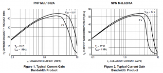
Most datasheets for transistors suitable for audio power amplifier output stages that I have seen, graph an "optimal ft" in the region of several amps Ic. Unless there is some other meaning to your post which I am missing, a consideration of the thermal issues resulting from that much current would generally render such biasing impractical.
Though I guess that the "Oliver bias point" does indeed become irrelevant if one is running Class A-level bias current.
Attachments
Though I guess that the "Oliver bias point" does indeed become irrelevant if one is running Class A-level bias current.
I simply meant more ft not peak ft, and by thermal issues I meant the 26mV number is directly proportional to temperature so at high dissipation it's the wrong number. Just saying maybe biasing a 100W amp at 50W quiescent is a better deal. The Oliver bias point has no use in IC's in general because the same emitter resistors are used to sense short circuit current and the 26mV makes the short circuit current limit too low over temperature.
Last edited:
But you wrote "optimal ft". In the context of a typical class AB power amplifier, how is there in any way a point of optimal balance between ft and the number of mV dropped across the emitter resistors?
Regardless of the number of mV dropped across the emitter resistors, more Ic = more ft all the way up until maybe three or four amps, at which point, for a 100W/8-ohm amplifier, we are approaching nearly an order of magnitude greater than 50 watts of quiescent dissipation.
Regardless of the number of mV dropped across the emitter resistors, more Ic = more ft all the way up until maybe three or four amps, at which point, for a 100W/8-ohm amplifier, we are approaching nearly an order of magnitude greater than 50 watts of quiescent dissipation.
But you wrote "optimal ft". In the context of a typical class AB power amplifier, how is there in any way a point of optimal balance between ft and the number of mV dropped across the emitter resistors?
I never made that connection, yes of course you can change the emitter resistor to match higher Ic but the 26mV number is for the output devices operating at 300K not their actual quiescent temperature.
As for optimum ft I simply meant having the speed of the output devices as an independent handle on frequency response and stability with no regard to the implications on the open-loop transfer function.
You wrote: "....output devices biased at optimum ft".As for optimum ft I simply meant having the speed of the output devices as an independent handle on frequency response and stability with no regard to the implications on the open-loop transfer function.
So am I now supposed to believe that by "optimum ft" you meant some figure considered independently of the actual biasing conditions (which of course influence the open-loop transfer function)?
Last edited:
You wrote: "....output devices biased at optimum ft".
So am I now supposed to believe that by "optimum ft" you meant some figure considered independently of the actual biasing conditions (which of course influence the open-loop transfer function)?
I frankly don't care what you believe (your choice of words is fairly hostile, why?), I consider phase margin over a range of complex loads and open-loop DC transfer function separate issues. You showed the graphs, how can ft be considered independently from Ic? If for some reason your amplifier is stable into a wider range of loads at 30Mhz ft rather than 12Mhz and that's what you want you bias at 500mA rather than 100mA and at that power level it's not 26mV anymore but it does depend more on ancillary issues like heatsinks etc. Simulations of open-loop transfer function without a simulator that includes T as a third independent variable are fairly useless at showing exactly what is going on for high power amplifiers.
Last edited:
Postscript - In Mr. Oliver's own words. If you don't have Thermaltrack devices his result is of little practical use. Besides that there was a tread here a few years ago with lots of sims showing ,as I have found, 26mV is never the right answer.
Another paper by Prof. Leach shedding doubt on another sacred cow gm doubling.
http://leachlegacy.ece.gatech.edu/papers/classab.pdf
Thus, unless the biasing diodes (see Fig. 4) track this change
within a few percent, Ic will be very unstable. If the
biasing diode were integrated on the same chip with the
transistor, accurate enough tracking might be achieved,
in which case these results would be of practical interest.
At present the most practical solution to the temperature
stability problem appears to be to make Re many
times larger than 1/go and to rely on negative feedback to
reduce the resulting distortion.
Another paper by Prof. Leach shedding doubt on another sacred cow gm doubling.
http://leachlegacy.ece.gatech.edu/papers/classab.pdf
I'm not strong in formulas and mathematics. What is the conclusion than for those who don't use thermaltracks? If to use 0.22R Re, what about Roender's FC-100 amp where he found the most optimal Re is 0.1R XOD wise with matched output devices (0.22R for not perfectly matched OPs).
How Geometric Mean biased output stages looks like?
Tnx.
How Geometric Mean biased output stages looks like?
Tnx.
- Status
- This old topic is closed. If you want to reopen this topic, contact a moderator using the "Report Post" button.
- Home
- Amplifiers
- Solid State
- One of the Top Solid-State CFA amp design