Yes but the Roender does including the MUR120 equivalent diodes which run around the outskirts in the image I posted.
These connect to the bases of a 2SC3423 NPN equivalent to Q1 in your simulation and a 2SA1360 PNP equivalent to Q20. These are in TO-220 packages and serve to increase compensate for the MUR120 temperature mismatch with the NJL transistor part of the die.
Having the sense element at the heat source is important to maintaining the correct level of bias which is difficult enough with one power device per output half let alone three.
Your choice of Q1 and Q20 transistors in TO-39 packages are small signal types as are D7 and D8. These are cheaper than the above mentioned parts, so consider why has extra money been spent on bulkier ones.
The next question is how to cover six temperature spots on the heatsink with a complement of four devices.
One possible answer would be to emulate the Roender by drilling holes adjacent to the power transistors to take MUR120s and fit TO-220 devices in lieu of TO-39's.
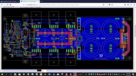
This is not Roender's layout. Perhaps you took it from FC100 builders thread. It's made by Rudi Ratlos from Germany, if I'm not wrong.
If I remember correctly, Roender said that these diodes works as they should only when they are built in on the same die in the transistor like the thermaltrack is, all other solutions with separate diodes attached are just not effective enough. The only choice in our situation is Vbe mult. I guess. If we would go the way you offer, simpler option can be to use diode in a small smd package glued to the collector lead instead.
Btw, it's TO-92 package, not TO-39 I'm currently using.
Can we exchange Q16, Q17, Q1, Q20, Q21, Q22 to 2SC3423 and 2SA1360? Here are the models.
.MODEL 2SC3423 NPN(IS=9.98627F BF=2K NF=967.67M VAF=100 IKF=49.6929M ISE=1.04163F NE=1.07574 BR=601.257M IKR=462.798U ISC=32.904P RC=899.97M
CJE=2P MJE=500M CJC=6.42174P VJC=749.999M MJC=499.509M TF=713.346P XTF=500M VTF=10 ITF=9.9976M TR=10N)
.MODEL 2SA1360 PNP(IS=10F BF=134.853 VAF=100 IKF=109.96M ISE=221.874F NE=1.66575 BR=10 IKR=880.176M ISC=187.58P NC=1.90472 RE=1 RC=15.5104
CJE=2P MJE=500M CJC=6.24728P VJC=692.028M MJC=340.013M TF=1.08385N XTF=16.9293 VTF=9.36211 ITF=670.025M TR=10N)
Last edited:
Actualy I already made one channel with bias setting by 1N4004 diode string wrapped by collector lead of OP transistors. As I can see this channel is more prone to ocsillation than with Vbe multiplier
Have you guys read about Hagermann's improved bias circuit? In my simulations it even improved harmonic behavior.
")
Cheers,
M.
Attachments
That bias circuit was covered in Doug Self's book.
Oh! I missed it.
Thanks.
M.
This is not Roender's layout. Perhaps you took it from FC100 builders thread. It's made by Rudi Ratlos from Germany, if I'm not wrong.
If I remember correctly, Roender said that these diodes works as they should only when they are built in on the same die in the transistor like the thermaltrack is, all other solutions with separate diodes attached are just not effective enough. The only choice in our situation is Vbe mult. I guess. If we would go the way you offer, simpler option can be to use diode in a small smd package glued to the collector lead instead.
Btw, it's TO-92 package, not TO-39 I'm currently using.
Can we exchange Q16, Q17, Q1, Q20, Q21, Q22 to 2SC3423 and 2SA1360? Here are the models.
.MODEL 2SC3423 NPN(IS=9.98627F BF=2K NF=967.67M VAF=100 IKF=49.6929M ISE=1.04163F NE=1.07574 BR=601.257M IKR=462.798U ISC=32.904P RC=899.97M
CJE=2P MJE=500M CJC=6.42174P VJC=749.999M MJC=499.509M TF=713.346P XTF=500M VTF=10 ITF=9.9976M TR=10N)
.MODEL 2SA1360 PNP(IS=10F BF=134.853 VAF=100 IKF=109.96M ISE=221.874F NE=1.66575 BR=10 IKR=880.176M ISC=187.58P NC=1.90472 RE=1 RC=15.5104
CJE=2P MJE=500M CJC=6.24728P VJC=692.028M MJC=340.013M TF=1.08385N XTF=16.9293 VTF=9.36211 ITF=670.025M TR=10N)
I think these devices have to be sourced from surplus stock suppliers but if you already have enough of them you can use these without the Tian stability plot being affected.
Since these types are used in the following stage you could bolt them on to the top insulated bodies of Q21and Q22 whose emitters are in the forward transfer path.
I also tried MJE340 and MJE350 since these are more common. These are 20 watt devices in TO-220 cases. When the transistor die sizes are similar you get a better heat transfer and the mechanical joint will not come undone.
The Tian plot does not change with these although the output stage dissipation reduces from 450 to 280 m.A. - I regard heat like fire you don't want it getting out of control.
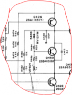
The Harman-Kardon HK870 from 1983-86 uses the same basic layout as employed here. It has some key differences which I would adopt including the bias setting part shown in the attachment.
Attachments
Bigun published his version of the Hagerman doubler here:
TGM5 - all-BJT Simple Symmetric Amplifier
Wahab recommended 2SC4495 as a better Tr for temperature compensation. Looking at the datasheet it seems it would hardly need a compensation resistor at the low currents we usually use...well, you know better how to read those plots than I can.
TGM5 - all-BJT Simple Symmetric Amplifier
Wahab recommended 2SC4495 as a better Tr for temperature compensation. Looking at the datasheet it seems it would hardly need a compensation resistor at the low currents we usually use...well, you know better how to read those plots than I can.
Attachments
Last edited:
Bonsai talks about thermal compensation on page 40:
http://hifisonix.com/wordpress/wp-content/uploads/2011/03/The_e-Amp_V2.03.pdf
Just to add to the pile.
http://hifisonix.com/wordpress/wp-content/uploads/2011/03/The_e-Amp_V2.03.pdf
Just to add to the pile.
Last edited by a moderator:
Dear Keantoken,
On the same subject, I wonder if you ever wrote that article about CFP compensation...from the "Optimizing the VBE multiplier" thread:
Cheers,
M.
On the same subject, I wonder if you ever wrote that article about CFP compensation...from the "Optimizing the VBE multiplier" thread:
Feedback theory may be all you need to make a circuit stable, if you are a master at math. But I don't know anyone who understands it well enough to confidently stabilize simple circuits such as the CFP. Don't you think that's strange? There are comparably expedient ways to understand stability.
My method of understanding stability is different but is still broadly applicable, and quite possibly less abstruse to the hobbyist. I would write everything here, but there is so much to tell I really want to write an article about it so things aren't fragmented and confused.
Cheers,
M.
I started on an article for Linear Audio and was progressing slowly with help from Jan. Unfortunately I didn't finish before Linear Audio closed. It has stalled, but in the meantime I am still learning, so I don't count it as such a bad thing.
I wonder whether there is any benefit to getting it published or if I will have the same results just putting it on my webpage.
I wonder whether there is any benefit to getting it published or if I will have the same results just putting it on my webpage.
Sorry for this slight OT, Andry.
I am interested because I don't care about emitter follower output: it sounds dull to me. Cascoded EF sounds better but nothing spectacular. I prefer common emitter/source (VFET ideally) or CFP (I imagine your compensation shoud also be good for outputs) and cascoded for that matter, which is a nightmare but sounds much like music, so I am studying and simulating and learning until I find my optimal output section or die trying...
Cheers,
M.
Well, I changed my mind about cascoded emitter follower output yesterday...by accident I discovered a trick in simulation that proved in real life to restore the magic in the sound. I have no clue about what is going on, though...
We live to learn.
I don't want to hijack so I will post my findings later in my own thread.
Best wishes,
M.
PS: by request--> The AMNESIS amp: a good amplifier, like a gentleman, has no memory.
Be aware that it is VFB Lin/blameless topology amp. I postponed further investigation on input and VAS to concentrate in output sections that can cope with the quality of the former...
Last edited:
Does anybody know why the sim isn't working?
Can we use A1312, C3324 PSpice models in LTSpice? They supposed to be the same as A970, C2240.
Check your .models for 2SA1360 and 2SC3423 for parameter changes between this simulation and simulation4.
- Status
- This old topic is closed. If you want to reopen this topic, contact a moderator using the "Report Post" button.
- Home
- Amplifiers
- Solid State
- One of the Top Solid-State CFA amp design