Hello good people.
I have an Yamaha AX400 that keeps changing bias voltage read around emitter resistors.
I turn the amp on, volume on min, no load or inputs, after 10 minutes i read 12mmv on left channel and 17-18mv on right channel (i'm aiming for 15mv, default/factory is 10-12mv), sometimes it starts with equal bias on both channels and sometimes is bias high on left and low on right channel. Readings are stable values for for 20-30 seconds for each 0.1mv step, then it starts slowly decreasing right channel and increasing in left channel. After 15-20 minutes the readings are the opposite, 18mv on left and 11mv on right. Some times this interval can be 30-40 minutes.
There's a time when the both read about the same around 14-15mv but the trend continues in cycles of about 20-25 (sometimes a more) minutes with a channel going up to around 18mv and the other going down to around 12mv.
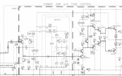
Is this normal behaviour? If not, what should be the culprit here? Q115 and it's equivalent on the other channel, Q116 are firmly attached to the main heatsink with fresh thermal paste.
I attached a schematic.
Note: the amp is modded with tone controls bypassed on the feedback loop but the bias "problem" was there before the mod.
thanks!
I have an Yamaha AX400 that keeps changing bias voltage read around emitter resistors.
I turn the amp on, volume on min, no load or inputs, after 10 minutes i read 12mmv on left channel and 17-18mv on right channel (i'm aiming for 15mv, default/factory is 10-12mv), sometimes it starts with equal bias on both channels and sometimes is bias high on left and low on right channel. Readings are stable values for for 20-30 seconds for each 0.1mv step, then it starts slowly decreasing right channel and increasing in left channel. After 15-20 minutes the readings are the opposite, 18mv on left and 11mv on right. Some times this interval can be 30-40 minutes.
There's a time when the both read about the same around 14-15mv but the trend continues in cycles of about 20-25 (sometimes a more) minutes with a channel going up to around 18mv and the other going down to around 12mv.
Is this normal behaviour? If not, what should be the culprit here? Q115 and it's equivalent on the other channel, Q116 are firmly attached to the main heatsink with fresh thermal paste.
I attached a schematic.
Note: the amp is modded with tone controls bypassed on the feedback loop but the bias "problem" was there before the mod.
thanks!
Attachments
Last edited:
Thank you very much for helping.
Nelson (the one and only") ): VR101, C161 and C163 are all new components as i did full re-cap and new multiturn pots. Note that the "problem" was there before the mods and recaps.
): VR101, C161 and C163 are all new components as i did full re-cap and new multiturn pots. Note that the "problem" was there before the mods and recaps.
Nigel: Drivers in this amp don't have heatsinks so i'll probably try that solution
Do you guys suggest any relatively simple(without destroying the pcb) mods to the circuit? All caps are good quality Panasonic FM's and Rubycon ZL's.
Nelson (the one and only
): VR101, C161 and C163 are all new components as i did full re-cap and new multiturn pots. Note that the "problem" was there before the mods and recaps.Nigel: Drivers in this amp don't have heatsinks so i'll probably try that solution
Do you guys suggest any relatively simple(without destroying the pcb) mods to the circuit? All caps are good quality Panasonic FM's and Rubycon ZL's.
Hi joaoveludo,
You have to understand that bias current is an approximate thing. You don't want it to lose control (thermal runaway), or be too low. I would leave it at the level set by Yamaha for starters. Also, checking bias is always done with the speakers disconnected so that DC offset will not affect your reading. It's okay to use the speaker switch to disconnect the speakers. No signal, so volume control all the way down as well.
Not a fan of multi-turn controls for bias, but also Yamaha put the pot in the wrong place. It should have been across the B-E part of the bias transistor with a fixed resistor between the C-B junctions. That way if the pot opens up (common failure mode), it causes the bias to drop down instead of going way high.
The advice given by Nelson is solid, and checking the voltage across R187 at rest will show you if there is something unstable in the diff pair. It's always nice to be sure everything is okay.
-Chris
it could be easier to solve this by replacing the NPN with a PNP so that the BE side is across the Variable Resistor............ Yamaha put the pot in the wrong place. It should have been across the B-E part of the bias transistor with a fixed resistor between the C-B junctions. That way if the pot opens up (common failure mode), it causes the bias to drop down instead of going way high..............
The two fixed resistors will need to be changed.
You are looking for a 6times Vbe multiplier.
change R183 to 470r, R185 to 2k7. That let's you keep VR=1k and give a Vbe range from 2.8times to 6.7times
Q115 can be any PNP that has the same pin out, but reversed and hFE>100.
How is Q115 attached to the heatsink?
Last edited:
Here's my two penn'orth: I find the best stability is with all drivers and output on the same heatsink. Taking account of the main heaters (the output transistors) thermal resistance, then the Vbe multiplier needs to be greater than 6 junctions. If the pre-drivers are TO-126, the drivers TO-220 and the output some sort of plastic TO-3 replacement, it should be possible, but the equivalent thermal resistance circuit needs to be drawn to check. Simple example: Rth j-c=1C/W, mounting=0.4C/W, heatsink=1C/W, the output transistors "see" 2.4C/W each, but the bias stabiliser only 1C/W (the heatsink). If the outputs dissipate 10W , the drivers 1W and pre-drivers 0.1W then the total power is 22.2W, raising the hs by 22.2C. The output junctions reach 32.2C, so shift 64mV while the d+pd rise only about 22C, or 44mV each, totalling 300mV for 22C rise needing 13.6mV/C=6.8Vbe's. A small resistor in series with the bias stabiliser
collector, before the base-collector resistor is added, can help to raise the multiplying factor.
But even then there will be some variations due to thermal lag (heating/cooling of junctions) and a variation in Iq is to be expected. The main issue I have seen is to check it stays above a minimum to avoid crossover distortion.
Last edited:
I read bias voltage with loudspeakers unconnected, Vol. @min and no source. The standard procedure.
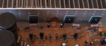
I attached picture of q115 and q116 on pcb and heatsink. I have not yet added heatsinks to the drivers but will try it. Cheap and won't hurt, i guess...
Ps: the picture is from a similar amp i got on google images. Mine has blue multi-turn pots.
On another completely different subject (sorry for slight off-topic), would emitter degeneration be beneficial to this input stage? The pcb has plenty of space to work some mods and two resistors can easily be placed.
thank you all.
Attachments
Last edited:
Care to elaborate why you're not a fan? These Bourns seem to work reliably. The others were a bitch to tune the bias, too twitchy and i was having problems with them. I would tune to 15mv and on the next day i would get readings of 30-40mv on one channel with one half of the heatsink clearly hotter if i moved or shaked the amp. That completely stopped with the new pots, that's why i changed them in the first place...
Ok, i was under the impression that emitter degeneration would have the opposite effect after reading Bob Cordell and Douglas Self books but i'm just learning about this craft and trying to understand the concepts.
thank you very much for the time.
Ok, i was under the impression that emitter degeneration would have the opposite effect after reading Bob Cordell and Douglas Self books but i'm just learning about this craft and trying to understand the concepts.
thank you very much for the time.
Hi joaoveludo,
Many multi-turn controls are the cheap Chinese variety. There are some good ones, but in general you are better off staying with the same type of control in this position. Now, yours may have been worn out and were problematic, but I have worked on tons of these amplifiers and never had a problem setting the bias current. Yamaha - yes, but not Cyrus / Mission (Cyrus made the Mission amps). Single turn controls are not cheap as many have suggested either.
Now, your wandering bias current wouldn't have changed like that with good single turn controls, plus bias current is an approximate quantity depending on temperature as well. You may have actually seen the fault that killed the output transistors. The regulators in these can oscillate because the decoupling capacitors, and filter capacitors go bad over time and with heat. It is possible that it was picking up the oscillation which resulted in high temperature dissipation in the outputs. This would be a very good thing to check. You need an oscilloscope for this test.
I hope you have it fixed for all time. Just understand that multi-turn controls are not better by default and are often not the right part for the job. You can easily restrict the authority of single turn controls. The one good thing about them is that you can tell with a look if they are in the normal range for the adjustment or not. You can't do that with multi-turn controls on a PCB (not the turn counting knobs you can get for panel mount).
-Chris
- Status
- This old topic is closed. If you want to reopen this topic, contact a moderator using the "Report Post" button.
- Home
- Amplifiers
- Solid State
- Unstable bias