Im trying to work out a fault with this and can't seem to get anywhere. Basically there is full rail voltage on the right channel output. Output deviced have all been disconnected and tested fine but the voltages seem to all wrong. I get rail voltage on both the collector and emitter connections and half voltage at the base which decreases over time I assume due to the 6001 bias throttling down.
The left channel seems ok with rail voltage on one side and nothing on the other although base voltage is high at 3v and the predrivers get incredibly hot within seconds.
I have gone through the circuit diagram and can't work out what's wrong.
I have checked all transistors by swapping from left to right channel and the 6001 chip and everything stays the same. I have reflowed the board to eliminate dry joints. I suspect an open resistor somewhere but they all.check ok in circuit.
Any ideas, I'm thinking of the voltage divider somewhere is open but I am right in thinking that this would still show as ok in circuit due to ti the way it works?
Have you reconfirmed the B-E voltage drop on all transistors in question ?
Did you compare voltage drops over the resistors with the other channel ?
If you have excessive current draw and heating, it be best to work with reduced line voltage e.g. use a variac so that you avoid additional damage.
Did you compare voltage drops over the resistors with the other channel ?
If you have excessive current draw and heating, it be best to work with reduced line voltage e.g. use a variac so that you avoid additional damage.
An externally hosted image should be here but it was not working when we last tested it.
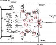
Circuit diagram with voltages measured, I can't understand why I have this problem on both of the output device pins. One showing positive and one showing negative. Ive been at this for months!
Any help much appreciated
I think we need more voltages than those two readings. Ten volts across the IC means it is trying to bias the output stage to destruction and not receiving feedback to 'turn the voltage' back down.
You should rig this up with a bulb tester to help prevent damage and perhaps even bypass the IC to force it to run as a conventional class b stage with no bias.
You should rig this up with a bulb tester to help prevent damage and perhaps even bypass the IC to force it to run as a conventional class b stage with no bias.
Voltage measurements are key to this fault...
You do need the outputs fitted because of the bias spreader IC.
Before you refit them, check to make sure all these marked resistors are OK. You can check them in circuit as long as the reading you get agrees with the value. If there is doubt then isolate one end.
Key voltages to begin with. Be sure to measure them all to confirm they are good.
1/ Collector of Q1. This should be positive rail.
2/ Collector of Q3. This should be negative rail.
3/ Voltage at the junction of the 0.22 ohm resistors
4/ Voltage on pin 13 of the IC.
5/ voltage on pin 9 of the IC.
6/ Voltage on pin 12 of the IC.
7/ Voltage on pin 10 of the IC.
Attachments
Measure on the faulty channel. I worked to this one with it having all the component values marked.
I would feel happier if you used a bulb tester... it really can save a lot of grief. All it is is a 100 watt mains filament bulb connected in series with the incoming mains to the amp. If the amp draws little current then the bulb is out and all the voltages come up. If there is a fault and excess current is drawn then the bulb lights, its resistance increases dramatically (hot filament) and that reduces the voltage supplies to the amp.
Also be sure NOT to connect speakers at any time while faultfinding.
")
1 - USE THE BULB TESTER - 40W globe initially is plenty probably.
2 - Reconnect B and E terminals of output transistors IOW disconnect Collector.
3 - Diode test ALL semis in output stage - if B-E and B-C measure 0.600 or so, and no shorted C-E junctions such transistors should be ok.....transistors can fail open but this is rare.
4 - Check ALL resistors in output stage - most are fusible type so may have failed open as protection.
5 - Power up and measure output DC offset and output transistor emitter resistor bias current match.
6 - If all is ok, Reconnect Collectors.
7 - Again measure measure output DC offset and output transistor emitter resistor bias current - set to spec in case of amplifier with Bias adjustment, ditto DC offset adjustment.
8 - Connect speakers and check operation with bulb limited AC supply....you may need to change bulb to higher power 60W, 100W.
9 - If all is ok, connect AC directly and recheck Bias and DC offset, allow amplifier to run with covers on and recheck bias and DC offset after 30 mins.
10 - Done.
I have fixed thousands of amplifiers by this rote recipe, quick efficient, perfectly effective....and you don't have to think too hard.
Hope this helps.
Dan.
Dan, the biasing arrangement on this amp is different to most in that it uses a bias spreader IC and not a traditional vbe multiplier.
If you disconnect the output stage collectors (assuming all else is good) then the drivers will attempt to deliver the full bias current via the B-E junction of the output devices. If that preset bias current (and the bias appears non adjustable) were say 100ma then the drivers would be dissipating 5 watts apiece and could fail.
If you disconnect the output stage collectors (assuming all else is good) then the drivers will attempt to deliver the full bias current via the B-E junction of the output devices. If that preset bias current (and the bias appears non adjustable) were say 100ma then the drivers would be dissipating 5 watts apiece and could fail.
- Status
- This old topic is closed. If you want to reopen this topic, contact a moderator using the "Report Post" button.
- Home
- Amplifiers
- Solid State
- Pioneer a616