Bogdan,
It was my opinion that I passed to X, and he saw no reason to disagree.
As has he mentioned, mosfets do not make good VAS in common source.
I don't believe this is incorrect, and is based from my personal experience, in particular, in the FetZilla, where a bipolar VAS is far superior to a ZVN, specifically in imaging. No reference to using common source output devices, although I don't that role much either.
Somewhat aggressive point you make. Why criticise X when he is on a roll, doing so much good work for the forum?
HD
Last edited:

Mofo PCB arrives tomorrow and I need preamplifier (B1 KORG work on progress).
Schematics attached. I know, xrk971 would prefer SMPS + BOOSTER + CRCRC.
My idea, 3x SMPS + CLC: 2x 24VDC@>4A for Mofo left/right and 1x 48VDC for AKSA/LENDER preamplifier.
Not ordered yet, comments welcome.
Final design (EAGLE binaries, Gerber and all manufacturing datas) will be available for DIY.
JP
Attachments
Yesterday I heard your fourteen amplifiers and I loved the F5 Juma sound.
Virtual Audition of Very Simple Quasi MOSFET Amp
Maybe the 15th would be the Cubie3
That's a nice amp, I agree. Perhaps it's liberated from the confines of a 2d flat PCB that makes it sing? Certainly, Juma designs some very nice amps.
Mofo PCB arrives tomorrow and I need preamplifier (B1 KORG work on progress).
Schematics attached. I know, xrk971 would prefer SMPS + BOOSTER + CRCRC.
My idea, 3x SMPS + CLC: 2x 24VDC@>4A for Mofo left/right and 1x 48VDC for AKSA/LENDER preamplifier.
Not ordered yet, comments welcome.
Final design (EAGLE binaries, Gerber and all manufacturing datas) will be available for DIY.
JP
Looks very good JP, it's the MoFo arrival that drove the rapid layout of this preamp. Couple of comments. On CLC, I have found adding a moderate value parallel resistor like 51ohms helpful to prevent that LC from oscillating. The output bypass caps should be film, it looks like you may have MLCC and that's not good as it has high distortion. I have not simulated with DN2540 yet so not sure what the values will be.
I wasn't criticising him, he was generalizing. I'm listening to a amplifier with mosfet vas, i tried bjt, but mosfet sounds better. In some sense it' simmilar to fetzilla... it's up to concrete aplication and a amplifier as a whole.Why didn't you use output mosfets in old aksa amps and use output bjts in new naksa amps? It is generalisation,period.🙂
My mistake, I have built Juma's F5 which did not use ZTX BJT and went straight from JFET to MOSFET gate. If original F5 uses the BJT for VAS then that is good and agrees with what I said about not using a MOSFET as a VAS. But I am no F5 expert so leave it at that.
Yes, original F5 uses bjt for vas, Juma ruined it with his mosfets 😀
@xrk971 Thanks for comments: output bypass is VISHAY/ROEDERSTEIN MKC1860 (very cheap at pollin.de).
JP
JP
Any ideas of why this is...the THD is not particularly different ?.......mosfets do not make good VAS in common source.
I don't believe this is incorrect, and is based from my personal experience, in particular, in the FetZilla, where a bipolar VAS is far superior to a ZVN, specifically in imaging.
HD
Dan.
Member
Joined 2009
Paid Member
In my very limited experience with Class AB amps the sound is especially sensitive to the VAS and what happens there (typically compensation but the VAS is often at a key juncture between the Class A input stage/error amp and the non-linear impedance of the output stage). It's waaay more than the THD can explain. The detailed nature of non-linear capacitances and operating curves are all important.
Low OLG amps can also be sensitive to the design of the error amplifier - LTPs work best with high OLG if you want to avoid large differential signals sweeping the LTP gain curve into non-linear regions.
Of course, for comparable OLG you need a high current through a FET VAS if you want to match the transconductance of a bjt... and a bjt wrapped up in Cdom is already quite linear.
Last edited:
Any ideas of why this is...the THD is not particularly different ?.
I'm also curious about this. My first guess is that it might have something to do with MOSFETs having much higher 1/f noise than bipolars. So low frequency details get lost, ISTM low freqs are very important to getting good soundstage depth.
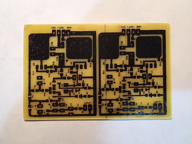
I just finished etching an SMT implementation in real FRP PCB. I had previously used the cheap phenolic or fiberboard ones. The layout was made by hand in PowerPoint and then laser printed for iron transfer.
Thermal transfer mask completed:
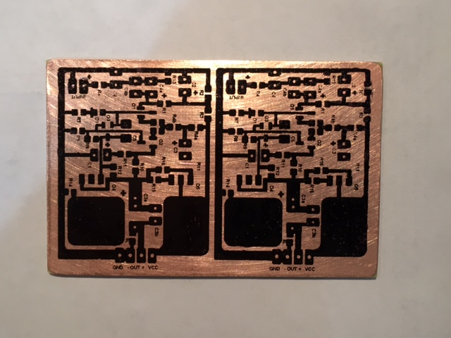
Etching completed:
Remove mask and drill through-holes completed:
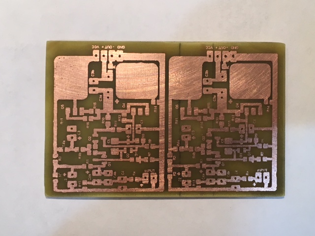
Ready to populate and reflow solder with a hot plate.
Thermal transfer mask completed:
Etching completed:
Remove mask and drill through-holes completed:
Ready to populate and reflow solder with a hot plate.
Attachments


In my very limited experience with Class AB amps the sound is especially sensitive to the VAS and what happens there (typically compensation but the VAS is often at a key juncture between the Class A input stage/error amp and the non-linear impedance of the output stage). It's waaay more than the THD can explain.
Dear Bigun!
you told what I thought yeasterday, I would only say that VAS noise shall be minimal to get good sq...
with respect
Off topic
Amplificateur USSA-5 : evolution de la conception de la version 4 - Page 6
Amplificateur USSA-5 : evolution de la conception de la version 4 - Page 6
1.1.5 USSA version 5:
This version is the same general topology as version 4 but has a CFP input stage and an improved CCS using 2 jfet instead of one. This is the latest crafted version of USSA and sound evaluation has not been performed at the moment of the writing of the manual.
...
1.1.7 F5-USSA:
This version is the same topology as the F5 thus uses the same number of parts and no modification to the F5 pcb required. However, input jfet transistors IDSS value have to be selected more precisely and output transistors are mosfet designed for audio (2SK1530Y/2SJ201Y) instead of IRFP240/IRFP9240 designed for switching. The gain is also 10 (as opposed to 5 for the F5) to allow to be the same as the other USSA versions and not require a preamp to reach the full available power. The damping factor is reduced from about 80 (F5) to about 30. The input current is also slightly reduced. The overall sound result is an improvement (more expressive bass and natural) over the standard F5 amplifier. "
Cool, that's what I was suspecting.I'm also curious about this. My first guess is that it might have something to do with MOSFETs having much higher 1/f noise than bipolars. So low frequency details get lost, ISTM low freqs are very important to getting good soundstage depth.
I completely agree that 1/f noise destroys depth image positioning and absolute depth of image LR width and positioning precision is reduced and center image is wider than it ought to be, also LR width and positioning precision is reduced and center image is wider than it ought to be.
It seems that signal triggers/drives 1/f noise, and this product noise triggers/drives a kind of 'avalanche' of 1/f noise throughout the rest of the system, and with tailing decay that is discernible.
1/f noise also causes modulation products.
Designing for lowest system 1/f noise is highest on the priority list if precision image focus and positioning, and clarity is the goal.
Dan.
Any ideas of why this is...the THD is not particularly different ?
I am not very sure about depth of image. I have noticed it's better with lower global fb designs; yet once when I put a tube into a SS AB fb amp the depth of image deepened hugely, so I'm not sure. It's possibly a psychoacoustic thing too, which might came back to phase shift and harmonic profile. But I'm guessing. I learn something about 1/f noise; but I'm not convinced about this either.
BTW, I NEVER generalise about generalities; they never get off the ground..... I prefer to talk about the general rather than the particulars, however, it makes nice small talk.
Ciao,
HD

Edit....that's what I was suspecting.
I completely agree that 1/f noise destroys depth image positioning and absolute depth of image, also LR width and positioning precision is reduced and center image is wider than it ought to be.
It seems that signal triggers/drives 1/f noise, and this product noise triggers/drives a kind of 'avalanche' of 1/f noise throughout the rest of the system, and with tailing decay that is discernible.
1/f noise also causes modulation products.
Designing for lowest system 1/f noise is highest on the priority list if precision image focus and positioning, and clarity is the goal.
Dan.
I think imaging and spatial cues are mostly related to minute changes in phase. Psychoacoustically, our ears are very sensitive phase detection devices. The strange asymmetric shape of our ears (folds and ridges etc) alter the phase of sound based on direction. A small 1mm length path perturbation induced by a small skin fold translates to maybe 3 microseconds alteration of the time of flight phase relationship). This allows us to locate direction of sound more precisely - even with one ear. Topologies that have very little feedback or no feedback have flatter phase, and I suspect a VAS stage with very high speed will have a flatter transfer function vs a VAS stage with lower speed. So even though we have hearing limited to 20kHz, I think there may be phase effects important to have an amp perturbing the phase as little as possible up to 1MHz even (microsecond resolution). Low level detail is important for recreating the level of ambiance and to some extent, phase contained in low level signals. But the main sound level is typically where the ear will "phase-lock" with to extract spatial content.
V1.7 with All SMT Components
I re-ran the simulation using some SMT parts: FJV1845 replaces KSC1845 and putting in a 600mA capable DZT5401 SOT223 package PNP for the KSA1381, and BC860 (same as BC857 model) and got an interesting improvement in the predicted THD. Recreating the 25k ohm load case at 20vpp drive, I am now getting 0.00074% THD, that's 7.4ppm I think. Compare that to my earlier 0.0031% THD using through hole parts. So, looking forward to building the little SMT version of this board then.
Predicted FFT for 20vpp into 25.3kohm load:
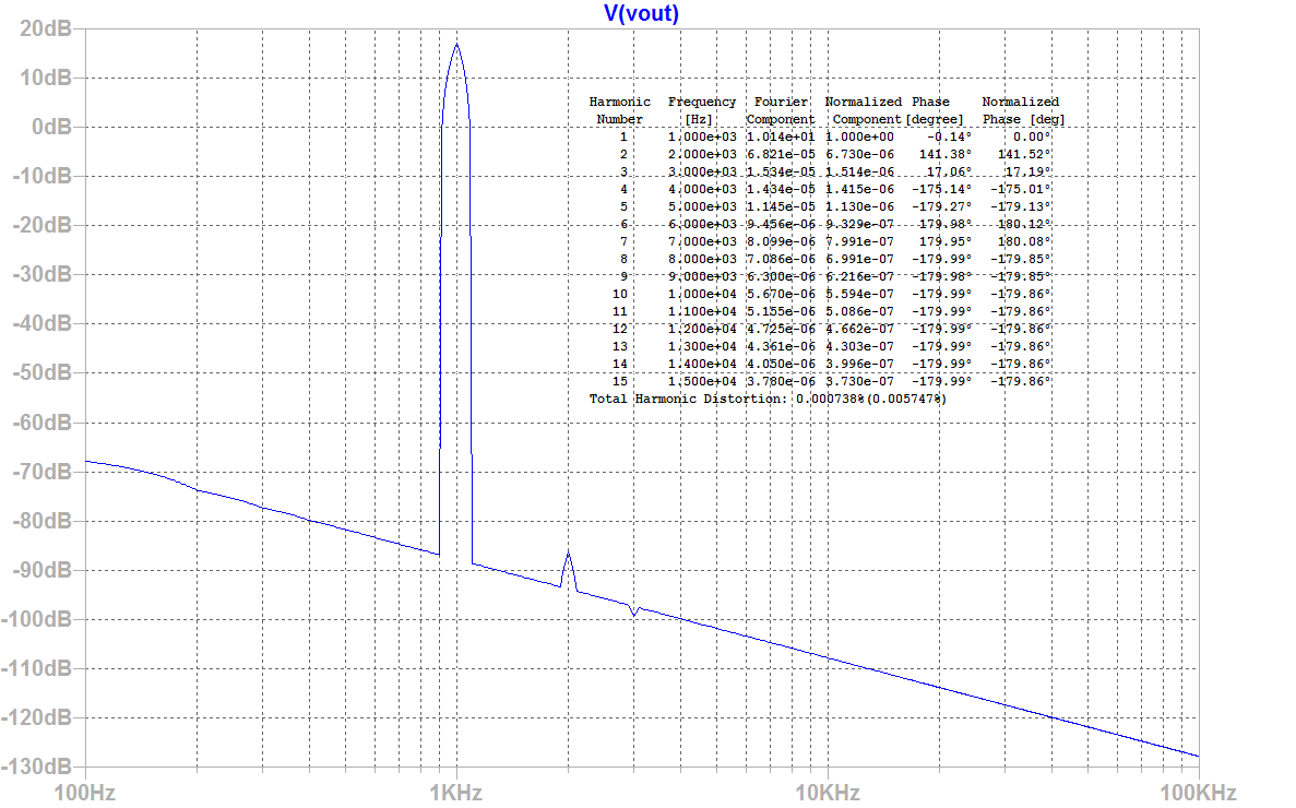
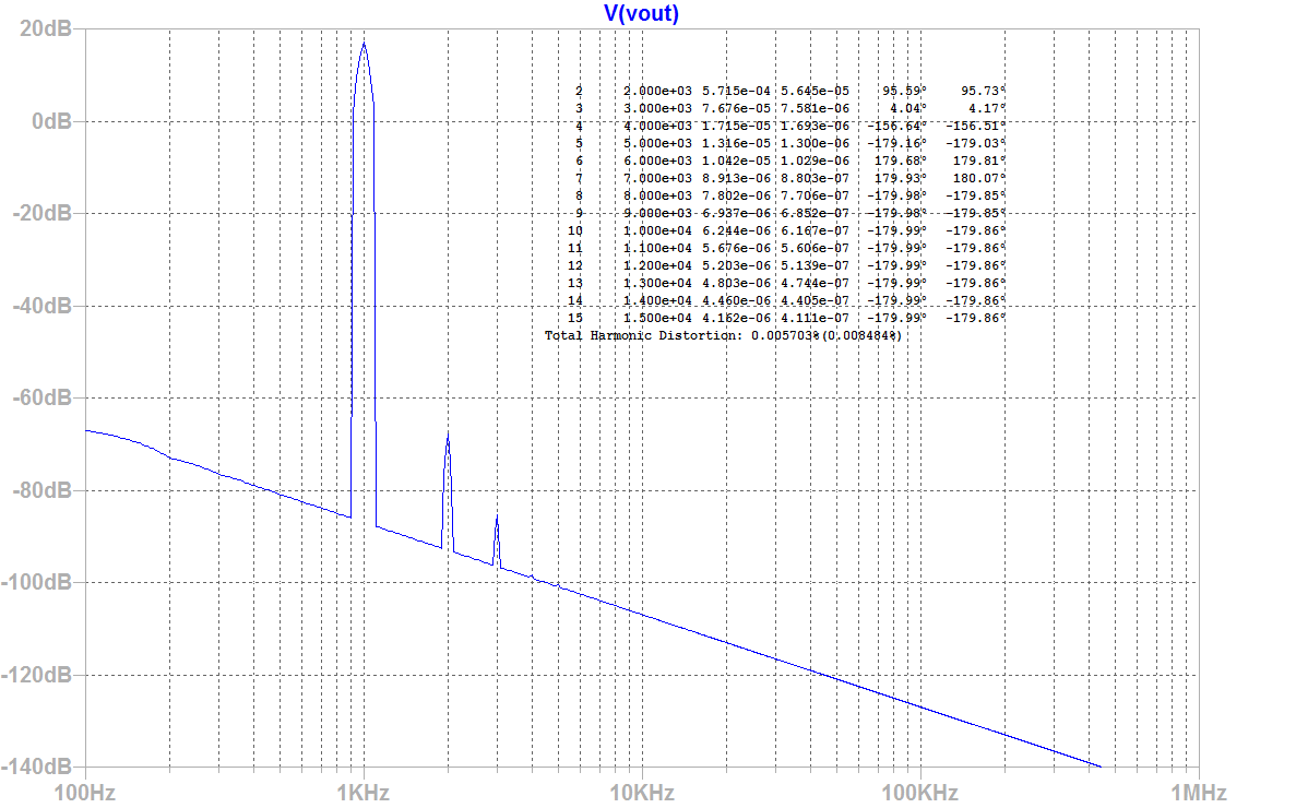
Now driving a 4.7kohm load to 20vpp, the THD is still a very low 0.0057% with nice profile:
I re-ran the simulation using some SMT parts: FJV1845 replaces KSC1845 and putting in a 600mA capable DZT5401 SOT223 package PNP for the KSA1381, and BC860 (same as BC857 model) and got an interesting improvement in the predicted THD. Recreating the 25k ohm load case at 20vpp drive, I am now getting 0.00074% THD, that's 7.4ppm I think. Compare that to my earlier 0.0031% THD using through hole parts. So, looking forward to building the little SMT version of this board then.
Predicted FFT for 20vpp into 25.3kohm load:
Now driving a 4.7kohm load to 20vpp, the THD is still a very low 0.0057% with nice profile:
Attachments


Last edited:
Hmm, it doesn't get any better than that.... outstanding results, X!
Wonderful harmonic profile, vanishing low, but significantly linear decreasing.
HD
Wonderful harmonic profile, vanishing low, but significantly linear decreasing.
HD
- Home
- Source & Line
- Analog Line Level
- AKSA's Lender Preamp with 40Vpp Output