GainWire mk3 CFA pre/phone amp with very low distortion
It is so complex that I can't get myself to finish building it.
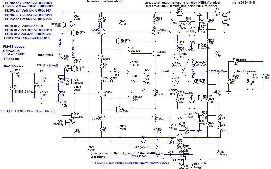
You can't call it complex, it's quite simple. Push yourself to finish it and you are going to be surprised by its sound. It's full stereo and power supply on one board (not showed in this schematic), that's way it looks complex.
")
Of course there is the £125000 Naim statement Naim Statement | Mono Power Amplifier | Naim NAP S1
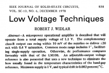
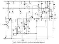
Schematic in post #4 comes from the IEEE Journal of Solid State Circuits, December 1978. There is indeed a second page of schematics. The schematic attached to Post #4 above, is the amplifier itself; the second schematic page (attached below) shows the only bias circuitry.I think I recognize the drawing style in post #4 (kind wanna say "schematic font") from old National Semiconductor ...
Also, I think there's more to it. Another page?
Where does the net Bias Buss go?
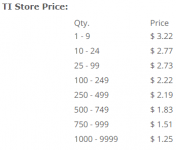
This 39 year old amplifier is still in production; DigiKey has hundreds on the shelf, and the TI Store will gladly sell you thousands.
_
Attachments
Onkyo TX-NR906 AV receiver.
no ground breaking technology here - but the total overall complexity packed into the box is pretty high. Probably others in the HT world with even more.
I don't want to spend the time counting all the duplicate and parallel features for weighting this but the 100 plus pages of parts may at least have them grouped for easy counting.
There are 31 pages of schematics like these 2 in a 336 page service manual.
Attachments
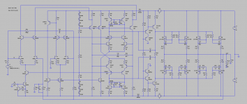
Personally, I'm totally into simplicity, so when I stumble across a diagram of a complex one, I'll get shiverings along my spine.
This is my favorite hate-object.
It's a project from the dutch magazine Elektor from around 2000.
Elektor was a magazine not mainly for audio projects, so there were probably a lot of well educated engineers in the staff. When a typical engineer starts to construct things he immediately violates all of the common known audiophile rules of thumb. Such as low NFB, simplicity etc..
I made one amplifier and one DAC from the Elektor, and non of them sounded any good.
The DAC was an ambitious one and used very expensive opamps, I remember.
At the end of the article, the author said something like this:
"This DAC has so utterly low THD that it's virtues are impossible to judge by a human ear".
But my ears complained and some months later I constructed a new analog section.
Attachments
Ha Ha! How about the first construction of that circuit Here. if I remember, that amp sounded really good
It was damn FAST too!!
Probably this amplifier. Click on the white "X" at lower left, to see it at full 100% magnification.
_
There are a National Semiconductor power amplifier chip, so this internal circuit diagram only was one monolithic piece, this thread look for some expensive audio amplifier circuits that's can show many of these monolithic circuits
Personally, I'm totally into simplicity, so when I stumble across a diagram of a complex one, I'll get shiverings along my spine.
This is my favorite hate-object.
It's a project from the dutch magazine Elektor from around 2000.
I think the impression of complexity in this Elektor design mostly results from both the voltage regulators and the triple 2nd VAS and drivers. Yes, and lots of current sources. Otherwise it's a rather straightforward design - diamond buffer with cascodes, 1st VAS, 2nd VAS, drivers, power devices. We even find something that is called CFA in this board.
I don't know why they opted for these triplications, though. Maybe they hadn't any more powerful driver devices in those days?
Best regards!
Really anything that uses a monolithic opamp, either in the signal path or as a DC servo, is going to have >50 transistors.
Even without using monolithic parts it's possible to build the transistor count up fairly quickly. Symmetrical differential topology involves plenty of transistors, and more so with copious cascoding. An amplifier that I've been playing with in simulation (that once upon a time bore some semblance to David Tilbrook's AEM6000) has 44 transistors, though I'm cheating a little by including a DC servo in that count.
Even without using monolithic parts it's possible to build the transistor count up fairly quickly. Symmetrical differential topology involves plenty of transistors, and more so with copious cascoding. An amplifier that I've been playing with in simulation (that once upon a time bore some semblance to David Tilbrook's AEM6000) has 44 transistors, though I'm cheating a little by including a DC servo in that count.
Attachments
Last edited:
Found it. The pinned out reference output gives it away.
Schematic in post #4 comes from the IEEE Journal of Solid State Circuits, December 1978. There is indeed a second page of schematics. The schematic attached to Post #4 above, is the amplifier itself; the second schematic page (attached below) shows the only bias circuitry.
This 39 year old amplifier is still in production; DigiKey has hundreds on the shelf, and the TI Store will gladly sell you thousands.
_
Mark Levinson Reference Amplifier
All of you are forgetting Mark Levinson Amplifier like Model 33 and even the old Model 27.5 that have schematics on web.
They are very good sounding amplifier with very complex schematics.
I had one very impressive audition with ML 33H with Wilson Audio Puppy.
Ronaldo
All of you are forgetting Mark Levinson Amplifier like Model 33 and even the old Model 27.5 that have schematics on web.
They are very good sounding amplifier with very complex schematics.
I had one very impressive audition with ML 33H with Wilson Audio Puppy.
Ronaldo
- Status
- This old topic is closed. If you want to reopen this topic, contact a moderator using the "Report Post" button.
- Home
- Amplifiers
- Solid State
- The most complex amplifier that you ever see