Gain is 2 * 22k/3.3k = 13.3 = 22.5dB
Load is 8 ohm unless stated otherwise, I probably forgot to say that.
BW is the measurement bandwidth of the AP. It is essential to know the measurement bandwidth when comparing results. Be very sceptical of THD numbers or plots where the measurement bandwidth isn't stated. It usually either means that they are trying to make the numbers look good for bragging/marketing purpose, or that they don't really know what they are doing. Especially THD20 numbers (THD @ 20kHz) depend a lot on whether the bandwidth is 80k or 500k or something else.
The parts arrived, I can now mount the MJL3281/1302 and LME49860 as intended. Also add regulators to set the opamp supply voltage to +23.4V/-21.4V.
And it still works and is stable, even without compensation cap! This is now a very high-bandwidth amplifier.
The optimal output stage idle current, for lowest THDN at 20kHz/5W/80kBW is now 75mA, which is _exactly_ the same as what LTspice predicted would be the optimal idle current! It is still less than what the "Oliver" current would be (104mA).
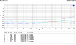
With the MJW3281/1302 and +-26V supplies, the amplifier clips at 90W/8ohm. The THDN with 22kHz measurement bandwidth is ~5-8ppm at all frequencies, probably hitting the noisefloor. With 80kHz measurement bandwidth the THDN is just around 8-15ppm at all frequencies.
Note the THDN measurement out to 100kHz with a 500kHz measurement bandwidth, 0.01% at 100kHz...
And it still works and is stable, even without compensation cap! This is now a very high-bandwidth amplifier.
The optimal output stage idle current, for lowest THDN at 20kHz/5W/80kBW is now 75mA, which is _exactly_ the same as what LTspice predicted would be the optimal idle current! It is still less than what the "Oliver" current would be (104mA).
With the MJW3281/1302 and +-26V supplies, the amplifier clips at 90W/8ohm. The THDN with 22kHz measurement bandwidth is ~5-8ppm at all frequencies, probably hitting the noisefloor. With 80kHz measurement bandwidth the THDN is just around 8-15ppm at all frequencies.
Note the THDN measurement out to 100kHz with a 500kHz measurement bandwidth, 0.01% at 100kHz...
Attachments
Thank you!
Yes 80kHz seems to be a de-facto standard. Does anyone know if this started with the AP1 or if some other test-equipment used this bandwidth before the AP1 came along?
That it didn't need compensation surprised me a little. The LTspice sim required about 10pF compensation to be stable, so it was close. I was expecting the actual hardware to be more difficult to stabilize than the sim.
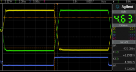
Here is a scope capture of a 100kHz squarewave. The blue curve is the input signal, the green and yellow are the two output phases.
There is about 2% overshoot which makes out to about 70 degrees phasemargin. It could be that some ringing is caused by the measurement setup, scope probe ground loops etc.
The slew rate is 7.2V / 420ns = 17V/us. Which is expected since the LME49860 has a specified slewrate of 15-20V/us. The slew-rate does not win any spec competition, but the full power bandwidth is still 140kHz. Should be enough")
Yes 80kHz seems to be a de-facto standard. Does anyone know if this started with the AP1 or if some other test-equipment used this bandwidth before the AP1 came along?
That it didn't need compensation surprised me a little. The LTspice sim required about 10pF compensation to be stable, so it was close. I was expecting the actual hardware to be more difficult to stabilize than the sim.
Here is a scope capture of a 100kHz squarewave. The blue curve is the input signal, the green and yellow are the two output phases.
There is about 2% overshoot which makes out to about 70 degrees phasemargin. It could be that some ringing is caused by the measurement setup, scope probe ground loops etc.
The slew rate is 7.2V / 420ns = 17V/us. Which is expected since the LME49860 has a specified slewrate of 15-20V/us. The slew-rate does not win any spec competition, but the full power bandwidth is still 140kHz. Should be enough
Attachments
Lowering the gain should lower THD even more, it is stable at 6dB of gain in each "leg", so 12dB of gain in total.
THD at 20kHz with 80kHz measurement bandwidth is then less than 8ppm for all levels up to 80W/8ohm.
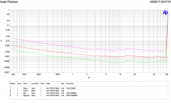
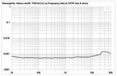
Does anyone remember the splash the Halcro amplifier made 15 years ago? It was hailed as the low-distortion benchmark of its time. The Stereophile measurement looks strikingly similiar to my own. Which indicates two things: Since the curves are so similar it indicates that my AP1 is ok. And with this amp I've reached the measurement limit of the AP1 just like Stereophile did with the Halcro.
THD at 20kHz with 80kHz measurement bandwidth is then less than 8ppm for all levels up to 80W/8ohm.
Does anyone remember the splash the Halcro amplifier made 15 years ago? It was hailed as the low-distortion benchmark of its time. The Stereophile measurement looks strikingly similiar to my own. Which indicates two things: Since the curves are so similar it indicates that my AP1 is ok. And with this amp I've reached the measurement limit of the AP1 just like Stereophile did with the Halcro.
Attachments
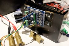
I forgot, here is a picture of the amp prototype. Says more than thousand words etc. I've been very happy with the separate PCBs for output stage and VAS, very easy to disassemble and make changes to the VAS. (And yes, I need to get a heatsink for those load resistors...)
Attachments
Excellent performances.
Using an op amp as a front end is IMO the way to go.
This does give performances that plainly fill the bill. There is no waste of time re inventing the wheel. This is true engineering that go at the real things. Taking care of:
Thermal stability.
Stability under wide real loads.
Repeatability, reasonable cost.
This class B amplifier performances are excellent and dependable.
Thank you.
Yes I think an opamp as an input stage has many benefits:
1. Low input offset voltage and no offset drift means you can avoid servos and AC-coupling capacitors and offset adjustment pots.
2. Low input bias currents means less constraints on resistors for input and feedback network.
3. No low frequency oscillation.
4. Low voltage noise and/or current noise without needing exotic transistors.
5. High GBW.
6. Low parts count.
The only drawback is the limited output voltage swing from most opamps.
So the only main non-linearity I am left with now is that of crossover distortion from a class-B output stage.
The thermal stability of my amplifier is pretty good but not perfect. I am using just a standard Vbe multiplier with the Vbe transistor on top of one of the output transistors. Since it's a bridged amp, there are two pots that need to be adjusted and kept in sync, that is a minor drawback.
I have taken some interest in autobias/sliding-bias output stages, I've done some simulations of existing designs but not found any that I am really happy with yet.
I see that I promised some plots earlier of THD vs various bias currents, that is coming up soon.
That is THD20 less than 4ppm for a single leg version for all levels up to 40W/4 ohm, a very interesting, very simple power amp.Lowering the gain should lower THD even more, it is stable at 6dB of gain in each "leg", so 12dB of gain in total.
THD at 20kHz with 80kHz measurement bandwidth is then less than 8ppm for all levels up to 80W/8ohm.
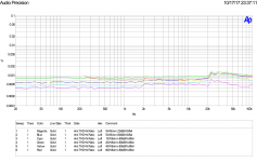
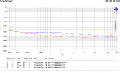
Here is the plot of THD vs amplitude for different output stage bias currents.
The blue line is underbias: 20mV over the pair of 0.25ohm emitter resistors.
The magenta line is the theoretical optimal bias quoted in several books of 26mV / Re.
The red line is the optimal bias adjusted for lowest measured THD. It comes out as 35mV in this case.
The yellow line is what happens when you try to bias the output stage into a "high-bias class AB". Clearly the worst above a few watts, and not better than the optimal bias voltage in the class-A region either.
Attachments
Very interesting.
I like to see, the optimal bias is quite far from the over tutted Oliver optimum bias.
I like to see, over biasing is no good.
You are at Gain 2 * 22k/3.3k = 13.3 = 22.5dB and load 8 Ohm ?
I wonder what you would get with a CFP output stage. Could you compare in simulation with a CFP version using same transistors. Optimal bias would be lower and I wonder about the THD behavior at low powers.
That is THD20 less than 4ppm for a single leg version for all levels up to 40W/4 ohm, a very interesting, very simple power amp.
On the contrary, the distortion for a single leg of the amplifier is higher than that for the bridged amplifier. There is some distortion cancelling going on with the balanced bridged configuration I think.
I wonder about the same, I have it on my todo list to try it out, perhaps make a CFP output stage PCB. I am a bit worried that I would need to add compensation caps to make it stable.mchambin said:I wonder what you would get with a CFP output stage.
The 8ppm THD20 plot is with 12dB gain.
Is your statement about simulation or about the real circuit ?On the contrary, the distortion for a single leg of the amplifier is higher than that for the bridged amplifier. There is some distortion cancelling going on with the balanced bridged configuration I think.
About simulation, I do not understand: The simulator calculates exactly the same signal with opposite phase at the two output legs. At the load the signal is doubled, the distortion too.
I do not see distortion cancelling....
Oups...I realise the positive side and negative side are not exact mirrors. The transistors are complementaries but don't have exactly the same cataractistics, and at the base spreader it is not symmetric too. This should not make much difference at high signal amplitude, but I am wrong to say there is exactly the same signal with opposite phase at the two legs.
So there can be some distortion cancelling.
Last edited:
I don't read the plots that way.Very interesting.
I like to see, the optimal bias is quite far from the over tutted Oliver optimum bias.
I like to see, over biasing is no good.
I see the optimal bias and the over biased as being near enough identical and both better than under biased all the way from very low levels up to ~-17dB ref maximum.
That's where we do much of our listening.
And when the high bias gets louder, the distortion is not as bad as under-biased until louder than -17dB ref max.
If one sets up the amplifier bias such that optimal is as low as it ever gets and any drift is towards the slightly over biased, then the plots show that one gets the best of all.
35mVbe to 52mVbe looks nice over the full range of all operating conditions, if this can be achieved.
And avoid underbias of 20mVbe and avoid 200mVbe.
Last edited:
Hi, I had a closer look at the input of your power amp.
I see it is a symmetric input, from a XLR plug I presume, at line level signals. Right ?
What about DC, I am not sure all line level XLR device output guarantee no DC at zero level. Such DC offset would set DC at the loudspeaker.
What if I want, a asymmetric input, will I add circuit to convert or do you plan a version to do so.
The first way would add, basically a dual amp and 3 resistors to do so. We end up with a total of 4 op amp. What components would you recommend to implement the first stage and gains at input stage and output stage.
The other way is revising the power amp in order to not add a front converting stage . This can be done using another feed back scheme. I wonder about stability and wether this reengineering is worthwhile ?
Last edited:
Is your statement about simulation or about the real circuit ?
Both. In simulation the difference is less, but it is quite clear what is going on. In the bridged circuit the even order distortion products cancel perfectly so there is only odd order products left.
In simulation for single amp at 40W/4ohm:
Fourier components of V(outp)
DC component:-0.000321149
Harmonic Frequency Fourier Normalized Phase Normalized
Number [Hz] Component Component [degree] Phase [deg]
1 2.000e+04 1.800e+01 1.000e+00 -0.30° 0.00°
2 4.000e+04 4.036e-05 2.242e-06 7.58° 7.89°
3 6.000e+04 7.694e-05 4.275e-06 -86.40° -86.09°
4 8.000e+04 1.133e-05 6.294e-07 -6.53° -6.23°
5 1.000e+05 5.547e-05 3.082e-06 -67.87° -67.57°
6 1.200e+05 7.857e-06 4.365e-07 28.53° 28.83°
7 1.400e+05 4.378e-05 2.432e-06 -72.47° -72.16°
8 1.600e+05 5.645e-06 3.136e-07 -0.47° -0.16°
9 1.800e+05 3.732e-05 2.074e-06 -61.78° -61.48°
Total Harmonic Distortion: 0.000661%(0.000000%)
Bridged amp @80W/8ohm:
Fourier components of V(outp,outn)
DC component:2.15484e-009
Harmonic Frequency Fourier Normalized Phase Normalized
Number [Hz] Component Component [degree] Phase [deg]
1 2.000e+04 3.600e+01 1.000e+00 179.54° 0.00°
2 4.000e+04 2.069e-08 5.747e-10 -141.89° -321.43°
3 6.000e+04 1.417e-04 3.936e-06 93.09° -86.44°
4 8.000e+04 3.338e-08 9.272e-10 -160.81° -340.35°
5 1.000e+05 9.064e-05 2.518e-06 113.91° -65.63°
6 1.200e+05 4.605e-08 1.279e-09 -168.38° -347.92°
7 1.400e+05 5.938e-05 1.650e-06 108.60° -70.93°
8 1.600e+05 5.821e-08 1.617e-09 -171.31° -350.85°
9 1.800e+05 4.336e-05 1.205e-06 127.20° -52.33°
Total Harmonic Distortion: 0.000510%(0.000000%)
In the measured amp the difference is greater. One other benefit with the bridged amp that does not show up in simulation is that there is no large signal currents in the ground path which can affect things.
35mVbe to 52mVbe looks nice over the full range of all operating conditions, if this can be achieved.
And avoid underbias of 20mVbe and avoid 200mVbe.
Agree.
Hi, I had a closer look at the input of your power amp.
I see it is a symmetric input, from a XLR plug I presume, at line level signals. Right ?
What about DC, I am not sure all line level XLR device output guarantee no DC at zero level. Such DC offset would set DC at the loudspeaker.
What if I want, a asymmetric input, will I add circuit to convert or do you plan a version to do so.
I have tested with XLR with differential drive, yes. But it works with single-ended inputs as well, just connect one of the input legs, does not matter which, to ground. No extra opamps needed. Beware that the input impedance gets quite low with the resistor values I used. The DC offset is very low from the amp itself, due to the low offset voltage of the opamp. But it will amplify any DC offset from your preamp. You can add AC coupling capacitors if needed.
Thanks to your simulations and Fourrier, it is clear the odd harmonics are doubled as expected and the even harmonics are cancelled.
No doubt, this interesting cancelling comes from the bridged topology, however I was enable to make a valid proof of this.
On a design, of my own using a LTC6090 and a CFP unity gain output stage, with massive feedback. My simulations show a different behavior at low powers. Below a certain power that depends of the chosen bias, the Thd decreases to extreme low as output power decreases.
This seems logical to me, since at low power the amp runs in class A and low amplitude signals linearize circuits around the operating point.
For instance with Rload 8 Ohm, Re 0.25 Ohm, quiescent current at 140mA, your amp runs in class A at output powers below 160mW.
I see your thd+n curves go increasing below 200mW, where in my simulations I see the contrary. What's wrong in my simulations ? Could that simply be because they give Thd, not Thd+N.
Will you add zobel networks and an inductor at output. I presume you prefer to put them outside the PCBs.
An inductor to cut at 80KHz 3dB will give you a substantial improvement of THD20.
You already have 0.0005%. With the inductor, I guess-estimated you can expect 0.0002%.
Nice little project! I have a bunch of 24vct (roughly 16-17 v per rail rectified) transformers laying around and was (at some point) going to build up something similar, although my power needs are less so was going to go instrument amplifier front end feeding a single ended ops and supply the opamp and driver from elevated rails so as to swing close to the output transistors rail. Oh and use 2sc5200/1943 instead.
My biggest concern will be figuring out a good clamp to soften clipping.
My biggest concern will be figuring out a good clamp to soften clipping.
The bridged topology does give a worthwhile THD improvement as pointed in post #33 and shown in post #37.
Here is a formal proof:
Assuming the two legs are exactly the same, with a sine input, the output signal outn is exactly the same as outp shifted half a period.
outn(t) = outp(t-T/2)
Then consider the Fourier decomposition of outp, one can see that, in out = outp - outn the even harmonics do cancel.
With outp = H1 + H2 + H3 + H4 + H5 +....
Provided, the two legs are the same.
out = 2*( H1 + H3 + H5 +.... )
- Status
- This old topic is closed. If you want to reopen this topic, contact a moderator using the "Report Post" button.
- Home
- Amplifiers
- Solid State
- Bridged Buffered Opamp Amp - a journey