Hi!
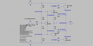
please take a look at the schematic part of output of Texan amp presented by Ian Hegglund in LAv13.
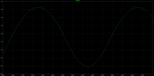
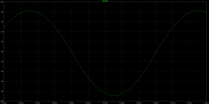
As you can see from the sinusoide look, it has the knee at descending part of the signal at around 1,8V.
Do you have the idea how to fix this knee? What part/set is for that?
Thank you in advance!
please take a look at the schematic part of output of Texan amp presented by Ian Hegglund in LAv13.
As you can see from the sinusoide look, it has the knee at descending part of the signal at around 1,8V.
Do you have the idea how to fix this knee? What part/set is for that?
Thank you in advance!
Attachments

Hi
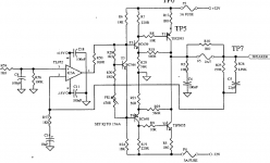
maybe do not connect R12 to the Base of Q1 - Q1 acts as emitter follower in this configuration...?
Solutions
* Bias voltage can also be generated via LEDs or diodes - more symmetric.
* or put two Resistors (or Bax16 tuning diodes) in series between the bases of Q3 and Q5, and feed the input via the middle
Also, there is no feedback in this circuit, but I think you are aware ;-)
I haven't read Ian Hegglun's Texan amplifier article but it would seem to me that though Q3,5 drivers do not source bias current from the power rails, other CFP designs do. Try adding 220R to the rails from the respective driver collectors and reducing the base stoppers, as shown in the Rega Brio for example and Douglas Self's "Audio Power Amplifier Design" handbooks.
Attachments
Last edited:
Hi
maybe do not connect R12 to the Base of Q1 - Q1 acts as emitter follower in this configuration...?
Solutions
* Bias voltage can also be generated via LEDs or diodes - more symmetric.
* or put two Resistors (or Bax16 tuning diodes) in series between the bases of Q3 and Q5, and feed the input via the middle
Also, there is no feedback in this circuit, but I think you are aware ;-)
Thank you, will check a little later!
I haven't read Ian Hegglun's Texan amplifier article but it would seem to me that though Q3,5 drivers do not source bias current from the power rails, other CFP designs do. Try adding 220R to the rails from the respective driver collectors and reducing the base stoppers, as shown in the Rega Brio for example and Douglas Self's "Audio Power Amplifier Design" handbooks.
Hi Ian!
this configuration do the trick with current drive of output transistors and act as (quasi)nonswitching circuit. If I add the resistors as you suggested, the magic will gone.
Current Drive Of Output Devices
The motivation for the design is detailed by the article "Current driven Output-stage class AB power amplifier" in the latest issue (Volume 13) of the Linear Audio bookzine. The main objective is to improve the thermal stability of the output stage and perhaps mitigate cross over effects. It is worth reading.
Apart from the article there was a thread in this forum a few months ago where Ian put forward and investigated a number of designs using simulations.
Adding resistors between the rails and Q3, Q5 will mean the output devices are no longer purely current driven by the drivers, which comprises the original objective.
Some of the waveform irregularity may removed by careful device selection as well as adding bleeders as proposed by Ian in this forum.
Regards ...
I haven't read Ian Hegglun's Texan amplifier article but it would seem to me that though Q3,5 drivers do not source bias current from the power rails, other CFP designs do.
The motivation for the design is detailed by the article "Current driven Output-stage class AB power amplifier" in the latest issue (Volume 13) of the Linear Audio bookzine. The main objective is to improve the thermal stability of the output stage and perhaps mitigate cross over effects. It is worth reading.
Apart from the article there was a thread in this forum a few months ago where Ian put forward and investigated a number of designs using simulations.
Adding resistors between the rails and Q3, Q5 will mean the output devices are no longer purely current driven by the drivers, which comprises the original objective.
Some of the waveform irregularity may removed by careful device selection as well as adding bleeders as proposed by Ian in this forum.
Regards ...
")
Hi
maybe do not connect R12 to the Base of Q1 - Q1 acts as emitter follower in this configuration...?
Solutions
* Bias voltage can also be generated via LEDs or diodes - more symmetric.
* or put two Resistors (or Bax16 tuning diodes) in series between the bases of Q3 and Q5, and feed the input via the middle
Also, there is no feedback in this circuit, but I think you are aware ;-)
Hi!
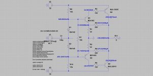
thank you again for this suggestion, with the diodes the knee on descending part of sinusoide has gone,
and the circuit has nfb, local and global
Attachments
- Status
- This old topic is closed. If you want to reopen this topic, contact a moderator using the "Report Post" button.
- Home
- Amplifiers
- Solid State
- Texan current drive from Linear Audio 13