This is most certainly a stupid question, but I have to ask:
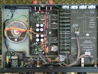
I bought a second hand Cambridge Audio A5 amplifier. Although I very much like its sound, I dont feel that it delivers the power that it should. The guy I bought it from did a modification. You can see the stock amplifier in the first picture, and the modified amplifier in the last two pictures. He put some resistors in there (the white ones). He said he did it to make it more reliable. Could that affect the power the amplifier delivers?
Thank you!
Attachments
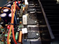
If you look at the schematic of the SAP15 type output pairs, they already have the correct value emitter resistor. Adding another unsightly looking resistor will reduce the output current of the amplifier below the designed specification. The usual failure of the SAP type transistor is the emitter resistor failing due to short circuit load conditions and this was a frowned upon quick bodge to get the amplifier going again by unscrupulous technicians trying to make an extra few quid by not having to purchase the pair of transistors but still charging for them!
It will not drive loads properly, if the SAP is not faulty and will, in some cases, increase distortion due to current clipping.
If they were needed, they would already be there!
It will not drive loads properly, if the SAP is not faulty and will, in some cases, increase distortion due to current clipping.
If they were needed, they would already be there!
He said that by removing one pin of the transistor he deactivated the internal resistor, and that he used the same value for the external resistor like the internal one.
He said that the internal resistor tend to overheat the transistor, that is why he did the modification.
He said that the internal resistor tend to overheat the transistor, that is why he did the modification.
He did it for the wrong reasons.
The internal resistor does not affect the overall temperature much as the resistor is bonded to the substrate and the heatsink keeps it cool along with the Darlington pair.
If the heatsink compound has dried out or is no longer conducting properly, that will be the reason the transistors overheat, not because of the internal resistor.
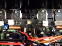
Removing the SAPs will ease replacement of heatsink compound and with clean solder pads will sit nicely in the board and become more valuable as an original amplifier.
I stock both types of SAP components, SAP15 and SAP16 as they are getting more difficult to find now as new old stock items if you come unstuck.
Check there is continuity between the internal resistor pins!
I stock both types of SAP components, SAP15 and SAP16 as they are getting more difficult to find now as new old stock items if you come unstuck.
Check there is continuity between the internal resistor pins!
R262 and R234 are responsible for the feedback gain control loop.
33k and 1k giving a gain of approximately 34 (R262 + R234 / R234) check they are the correct values.
SAP15 are good transistors when used within their ratings and do not affect the sound quality east electronics. You of all people should know that.
33k and 1k giving a gain of approximately 34 (R262 + R234 / R234) check they are the correct values.
SAP15 are good transistors when used within their ratings and do not affect the sound quality east electronics. You of all people should know that.
Welcome to the electronic repair hobby. I learned by doing then looking up the reasons for the problems I was having.
Gain doesn't usually deteriorate due to time. It is not set with pots, it is set with fixed resistor. volume is set with an input pot, decreasing the value of the input voltage with a resistor devider. Those pots do go bad sometimes.
Output power does deteriorate with time frequently. Measure your output power at maximum gain with an 8 or 4 ohm resistor (depending on the rating in the manual) checking the voltage developed with an analog voltmeter (not digital). I use 10 ohm variable tap 250 watt ohmite resistors I bought in the 1980's. But those are very expensive now, it is cheaper to build up a load out of .5 ohm 25 W resistors or something else cheap. Power is (V^2)/Z where Z is speaker impedance. (resistance of the load resistor). I use a transistor radio with an earphone jack for exciting the amp for load test, but not at full volume 7 vac , lower at about 2 vac input usually.
If output power is low, usually either one of push pull output transistors is bad, or rail caps (the big ones rated at the highest voltage) are dried up.
I'm with East electronics, darlington output transistors tend to overheat and thermally run away worse than simple transistors with driver transistors on a separate heat sink. Then they burn up. With a board designed for darlingtons, it is usually easier to salvage the case and power supply transformer and install a new board. If this amp has input sections like a preamp and a selector switch for various sources, you can sometimes salvage that section and intall a new power stage board.
Plus with diy you can put in an output fuse or mosfet protection board to protect the output transistors if you step on a wire and short the output, or a speaker driver loses the rubber surround and shorts a turn.
BTW if you want to repair a seriously well designed amp, buy a blown up PA amp from Peavey, Crown, QSC, Yamaha. One from the nineties or earlier with leaded parts and class AB output. Class D amps (modern) are for pros with serious equipment and training. I learned on old dynaco relics, the equivalent in UK are Leak.
Last edited:
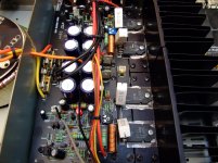
They are RV201/202 and adjust the quiescent current for the output transistors.
I think you will find the blue one is the one that has been changed.
They both could do with being changed as they do go odd values and cause failure of the SAP transistors. They MUST be set up as per the service manual!
I think you will find the blue one is the one that has been changed.
They both could do with being changed as they do go odd values and cause failure of the SAP transistors. They MUST be set up as per the service manual!
Last edited:
To make the basics clear to newbies, "quiescent current for output transistors" means both the push and the pull are turned on at the same time. This eliminates the turn on turn off switching noise (crossing distortion) which was very annoying in early design push pull transistor amps. Both transistors leak a little, are turned on even when no music is passing through. The small leakage current is also called "idle current" and is typically 10-40 ma across the .22 ohm emitter resistor for this size transistor pair.
- Status
- This old topic is closed. If you want to reopen this topic, contact a moderator using the "Report Post" button.
- Home
- Amplifiers
- Solid State
- Question regarding amp mod