I also have another SMPS but it is much higher voltage, +/-58Vdc
I can definitely wait for Valery to run some simulations.
Do
Hi Do,
Can you please measure the following voltages:
1) Test Point TP2 referenced to Ground;
2) Voltages across R22, R23 (220R each).
Thank you,
Valery
I will definitely do this but with earlier experiment of paralleling 1K 2W resistor on top of R17-R18, gave me a solid 15.5V on the D3-D4 Zeners, however, I still had the same issue of 14V offset and at max pot setting was able to adjust to 1.3V.
I will replace those resistors for sure and also get the measurements you requested as soon as possible.
I will replace those resistors for sure and also get the measurements you requested as soon as possible.
Hi Valery,
I have temporaly added 2k 5w resistor in parallel to R17-18 so that D3-4 gets 15V.
Here's the measurements you requested (keep in mind that DC offset has not been adjusted since the best I can do with the 200R pot is 1.3V but now it is at 14V...
TP2 = -13.50V
R22 = 2.775V
R23 = 1.601V
Thanks
Do
I have temporaly added 2k 5w resistor in parallel to R17-18 so that D3-4 gets 15V.
Here's the measurements you requested (keep in mind that DC offset has not been adjusted since the best I can do with the 200R pot is 1.3V but now it is at 14V...
TP2 = -13.50V
R22 = 2.775V
R23 = 1.601V
Thanks
Do
Valery, Do,
I am hoping that lots of people build the SimpleStark and publish their subjective impressions, which really make or break a DIYaudio.
I know from my work with fb and SS amps that this design sounds very, very good.
As the late Charles Hansen (founder of Ayre) said:
'One you hear a zero global fb amplifier you can never go back'.
Take a bow, Valery, one of the best amps on the forum!
Hugh
Hi Valery,
I have temporaly added 2k 5w resistor in parallel to R17-18 so that D3-4 gets 15V.
Here's the measurements you requested (keep in mind that DC offset has not been adjusted since the best I can do with the 200R pot is 1.3V but now it is at 14V...
TP2 = -13.50V
R22 = 2.775V
R23 = 1.601V
Thanks
Do
Hi Do,
Can you please measure at you best 200R pot position (same 3 measurements). Then, there are 2 resistors in series on each side of the pot - 180R and 100R. On the side where your pot's wiper will appear in the best position, short the 100R with a jumper wire. On the other side - replace 100R with 200R (you can just add another 100R in series with it for now).
This will allow you to zero-out the offset.
Cheers,
Valery
Valery, Do,
I am hoping that lots of people build the SimpleStark and publish their subjective impressions, which really make or break a DIYaudio.
I know from my work with fb and SS amps that this design sounds very, very good.
As the late Charles Hansen (founder of Ayre) said:
'One you hear a zero global fb amplifier you can never go back'.
Take a bow, Valery, one of the best amps on the forum!
Hugh
Hi Hugh,
Thank you
") It's really the best-sounding amplifier I have.
It's really the best-sounding amplifier I have.My prototype is in France now, being tested with Davis Acoustics speakers with very good results.
Cheers,
Valery
Attachments
Valery,
Let me ask you... Would it be preferable we test it with the intended voltage (+/-48Vdc) but maybe not ideal for a 4 ohm load though? If you prefer we continu with the +/-39Vdc then no problem at all.
Thanks
Do
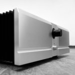
BTW, what volume control do you use on the picture above? Is there a preamp in there? Looks really nice!
Let me ask you... Would it be preferable we test it with the intended voltage (+/-48Vdc) but maybe not ideal for a 4 ohm load though? If you prefer we continu with the +/-39Vdc then no problem at all.
Thanks
Do
BTW, what volume control do you use on the picture above? Is there a preamp in there? Looks really nice!
If turning the pot all the way clockwise, then short R13 and change R10 with 200R, correct?
Exactly, if your wiper is in the "bottom" position, looking at the schematic.
Valery,
Let me ask you... Would it be preferable we test it with the intended voltage (+/-48Vdc) but maybe not ideal for a 4 ohm load though? If you prefer we continu with the +/-39Vdc then no problem at all.
Thanks
Do
BTW, what volume control do you use on the picture above? Is there a preamp in there? Looks really nice!
Let's keep +/-39V - no problem. Certain disbalance in the IPS is not related to the rails voltage, although we have never experienced this kind of issue before.
No problem - let's just try to move the trimming range, shorting the 100R resistor on one side and adding it to the other side - I think in this case you'll be able to zero-out the offset.
The volume pot on my prototype is not connected to anything right now - it's just covering the hole in the front panel
However, I plan to add it as a simple passive attenuator in the future - it's an ALPS 50K audio pot at the input.
Cheers,
Valery
Looks like it is working now. Only first PCB tested but offset is very adjustable.
Just curious though, I thought I bought matched Jfets but were they matched N and P? I'm asking since the P or N were still in the cut tape and the other ones were bulk. Could this be the imbalance/offset issue? Honestly, can't remember really remember if they were supposed to be matched or not, please don't quote me on this... Brain fart..!
Could I use matched J74/K170 instead? If yes, which grade and Idss?
Now I've adjusted bias and waiting for everything to stabilize...
Do
OK, good.
Don't worry about certain static difference between the positive and negative halves of this symmetric front-end. As we know, complementary pairs are not as complementary as we would like them to be. In many other designs, we have a servo to take care of the offset, and we normally don't care how much offset we have at the servo output when the system is balanced
"No global loop" design like this with only 18db ODNF loop gain is rather sensitive to Vgs and Vbe parameters of all the active devices in the circuit.
It's not necessarily the jFETs - certain static offset may be caused by anything.
I expected this kind of situation in some builds - that's exactly the reason I have 100R and 180R resistors in series on each side of the offset trimmer, making the trimming range adjustment easier.
k246/j103 are the best for this design as-is, other jFET pairs may require adjustment of R5, R6, as well as the whole chain of R10-R13.
Now, as soon as you're done with static settings, you'll need to set the ODNF error signal to its minimum level, adjusting R26, having 5-10V RMS of 1KHz signal at the output with the load connected.
Then you can move on to listening - I'm interested in your impressions
Try some hi-res tracks with acoustic instruments at the normal listening levels - that's where you normally "hear the most of a difference"
Scope adjustments are done, first module is now playing music!
R15 - R18 dissipate quite a lot of heat, they're 2K 2W resistors and reaching ~50 Celcius, that's ok?
~50 Celsius is fine - those resistors in my prototype are also pretty warm.
Heh - my long post took some time, so your post about the scope adjustments came in a bit earlier
Not a problem!
I'll wait until I get my speaker protection PCB to listen to the amplifier on my main speakers, in the meantime, I'll use another set of speakers. I still need to do the second module and change those components permanently so it looks all good.
Do
- Home
- Amplifiers
- Solid State
- No-global-loop amplification