Hi Guys.
This is an add on side post from my post here -> http://www.diyaudio.com/forums/multi-way/312641-dynaudio-identification-help-required.html
In essence I have a pair of active speakers I've been asked to rebuild.
I know close to nothing about these speakers/amplifiers other than they need a lot of work.
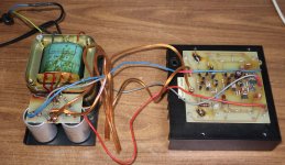
All the pencil and marker writing is from whoever worked on them in the past.
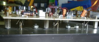
I can see that the outputs are all 2n6758's, and that it uses two for the tweeter, and four for the bass driver.
If anyone can give me any schematics, info or advise regarding the amplifiers, final setup (biasing), suggestions for reliability or performance modifications, I would be very grateful.
My only plan of attack at present is to repair the damage as best I can, uprate parts in heat affected or burnt areas, full recap.
This applies to amp modules as well as power supplies.
Also thinking of putting a CL60 on the transformer to help soften the increased start up surge when I replace the power supply caps.
We're 240vac here, and the transformers are rated as 220vac.
Note - Under the boards at the main burn damage is another resistor.
When I have the boards separated from the outputs/heatsinks I will post pics of the undersides.
This is an add on side post from my post here -> http://www.diyaudio.com/forums/multi-way/312641-dynaudio-identification-help-required.html
In essence I have a pair of active speakers I've been asked to rebuild.
I know close to nothing about these speakers/amplifiers other than they need a lot of work.
All the pencil and marker writing is from whoever worked on them in the past.
I can see that the outputs are all 2n6758's, and that it uses two for the tweeter, and four for the bass driver.
If anyone can give me any schematics, info or advise regarding the amplifiers, final setup (biasing), suggestions for reliability or performance modifications, I would be very grateful.
My only plan of attack at present is to repair the damage as best I can, uprate parts in heat affected or burnt areas, full recap.
This applies to amp modules as well as power supplies.
Also thinking of putting a CL60 on the transformer to help soften the increased start up surge when I replace the power supply caps.
We're 240vac here, and the transformers are rated as 220vac.
Note - Under the boards at the main burn damage is another resistor.
When I have the boards separated from the outputs/heatsinks I will post pics of the undersides.
Attachments
for bad caps and resistors: repeal and replace.
When in doubt, change it out.
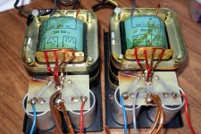
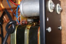
The transformers look just fine to my eye. The brown liquid is from the process of making the trans's
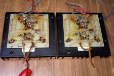
the boards look custom to me. Dunno 'bout schematics. It looks in really damn rough shape though.
When in doubt, change it out.
The transformers look just fine to my eye. The brown liquid is from the process of making the trans's
the boards look custom to me. Dunno 'bout schematics. It looks in really damn rough shape though.
Pretty much what I think I will have to do. Everything.
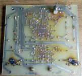
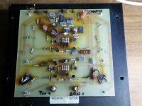
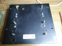
I note with interest the foil side of the board has 'Dynaudio V 4 0 0' and some sort of maker mark (bottom right corner).
So obviously genuine.
I was led to believe these speakers are 2002.
But the parts and construction suggest way earlier to me.
Maybe early 90's or maybe even late 80's.
Power supply.
Transformer as you say is fine, just the varnish.
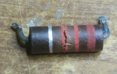
The carbon bleeder resistors are cracked right through, but amazingly measure ~2.4K ohm.
The caps, one on either side are starting to vent yet still all measure ~ the 9,000uf (Their labelled 10,000)
Lots of work to do....... :|
Please excuse these phone pics as my main camera battery is on charge. Doh.
I've left the two board pics large for those that want the extra resolution.
I note with interest the foil side of the board has 'Dynaudio V 4 0 0' and some sort of maker mark (bottom right corner).
So obviously genuine.
I was led to believe these speakers are 2002.
But the parts and construction suggest way earlier to me.
Maybe early 90's or maybe even late 80's.
Power supply.
Transformer as you say is fine, just the varnish.
The carbon bleeder resistors are cracked right through, but amazingly measure ~2.4K ohm.
The caps, one on either side are starting to vent yet still all measure ~ the 9,000uf (Their labelled 10,000)
Lots of work to do....... :|
Please excuse these phone pics as my main camera battery is on charge. Doh.
I've left the two board pics large for those that want the extra resolution.
Attachments
{snip}....I was led to believe these speakers are 2002.
But the parts and construction suggest way earlier to me.
Maybe early 90's or maybe even late 80's.
The power transistors are 1991. Some chips are 1988.
I once had a Willys built 1961 of bottom-bin leftover parts from the 1950s. It is not impossible a small maker over-bought parts in 1991 and didn't use them until 2002. But very odd.
This one has been messed with SO much, I'd be tempted to scrap all but the transformer and heatsink, find some other guts to work at same voltage and power.
Suggest that you sketch a schematic for each (identical) PCB and compare to catch any mistakes.
It looks like each PCB contains two amplifiers, and four opamps (IL072CP = dual opamps with JFET inputs) which create the active crossover filter between them. Maybe.. two output transistor pairs for the woofer, and one output transistor pair for the midrange-tweeter.
The input stage looks like a differential pair with a resistor current source and resistor emitter loads, one which then drives an emitter follower VAS transistor stage above a bipolar current-source. The last two bipolar PNP and NPN transistors are the output drivers, with a round 1-turn variable resistor between to set the output bias. A very basic amplifier topology.
I'd be inclined to say remake the whole lot. The PCB is badly burned, and where it has carbonised you will need to cut that away to prevent issues.
The tricky bit would be to determine what the electronic crossover network is doing.
As you're in Oz I would highly recommend some of Rod Elliot's projects for this job. He has some nice electronic crossovers, and the P3A/P68 amplifiers would be good fit too
The tricky bit would be to determine what the electronic crossover network is doing.
As you're in Oz I would highly recommend some of Rod Elliot's projects for this job. He has some nice electronic crossovers, and the P3A/P68 amplifiers would be good fit too
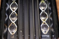
Hm, the transistors are actually MOSFETs.. military versions of the IRF230. From your pictures I am not seeing where the bias transistor is on the main heatsink... maybe it didnt have one on the heatsink which is Very Bad.
edit: I wonder if the original amplifier had lateral FETs (which dont require Vgs multiplier thermal feedback) and someone has replaced them with the HEXFETs here... and that is what has led to the damage. I would say at least one pair of MOSFETs will be dead - the two underneath the big burn marks will have bought it!
I think the next best thing to do is reverse engineer one of the PCB's. It will soon become apparent what kind of output devices the amplifier should have had. I am pretty sure they were supposed to be laterals given that there is no bias devices on the heatsink.
Last edited:
Suggest that you sketch a schematic for each (identical) PCB and compare to catch any mistakes.
It looks like each PCB contains two amplifiers, and four opamps (IL072CP = dual opamps with JFET inputs) which create the active crossover filter between them. Maybe.. two output transistor pairs for the woofer, and one output transistor pair for the midrange-tweeter.
The input stage looks like a differential pair with a resistor current source and resistor emitter loads, one which then drives an emitter follower VAS transistor stage above a bipolar current-source. The last two bipolar PNP and NPN transistors are the output drivers, with a round 1-turn variable resistor between to set the output bias. A very basic amplifier topology.
Mm yes no I won't be sketching it out, I suck badly at that so it would take me a month and would be badly wrong

Two amps (bass 4 outputs, tweeter 2 outputs) active crossover. Two ways system.
I'd be inclined to say remake the whole lot. The PCB is badly burned, and where it has carbonised you will need to cut that away to prevent issues.
The tricky bit would be to determine what the electronic crossover network is doing.
As you're in Oz I would highly recommend some of Rod Elliot's projects for this job. He has some nice electronic crossovers, and the P3A/P68 amplifiers would be good fit too
Yes I've looked into replacement sections.
But I have to keep the costs down. Otherwise I'd swap in the mini dsp two channel plates.
I'd say they let the smoke out many years ago, hence why its got different replacement parts from one to the other.
Same values, just different brands and styles of repair work.
Due to this, I'm thinking they've been repaired several times by different people.
Lets face it, we all know those 'ero' caps are the first thing that need to go..
Testing the outputs on the heatsinks, they all measure perfectly.
But, after stripping the heatsinks/outputs, it turns out that on one unit, 4 of the 6 outputs are unlabelled.
Strange thing is, the underside of boards, the soldering, lack of residue, way component legs are bent over and uniformly trimmed.
It confuses me as it all looks too uniform not to be factory.
Yet some caps and resistors are different brands between the two boards.
Hm, the transistors are actually MOSFETs.. military versions of the IRF230. From your pictures I am not seeing where the bias transistor is on the main heatsink... maybe it didnt have one on the heatsink which is Very Bad.
edit: I wonder if the original amplifier had lateral FETs (which dont require Vgs multiplier thermal feedback) and someone has replaced them with the HEXFETs here... and that is what has led to the damage. I would say at least one pair of MOSFETs will be dead - the two underneath the big burn marks will have bought it!
I think the next best thing to do is reverse engineer one of the PCB's. It will soon become apparent what kind of output devices the amplifier should have had. I am pretty sure they were supposed to be laterals given that there is no bias devices on the heatsink.
My search says those outputs are mosfets. See my note above about four unlabelled outputs.
The burnt section (resistors) are in the section with two outputs only, so I'm pretty confident that'd be the tweeter amp.
One board has new resistors on top, other board they've been put on underneath.
Both have those tracks fubar'ed so I will need to do some scraping, cutting, rerunning in that area.
I'm about to send dynaudio an email.
HA. lets see if that even gets a response...............
Well, that f that idea :|
Thought I'd remove some caps so I can get at the zeners better.
Oh joy.
The board is one of those where at the sight of a soldering iron the tracks fall off.
Not just one track, every. single. one. I. touched.
Too old for this sort of nonsense.
I've emailed the owner with the options of going passive or using the two way ice/mini-dsp plate amp.
For those playing at home.........
Dynaudio got back to me.
They passed the photos around and no one knows these speakers.
Their best guess is they were one of their very first active speakers built around late 70's early 80's.
They can still supply drivers, which is pretty awesome in it's self, but that's the end of what they can do.
Otherwise the owner and I are still in discussion as to the next step.....
Maybe just accept they have reached the end of a useful life.
The pic showing the mains transformers shows the primary wires passing over a metal edge.
That would never be passed as "safe" in my builds.
The wires need an extra layer of robust insulation and the potentially sharp edge needs some form of protection.
The pic showing the mains transformers shows the primary wires passing over a metal edge.
That would never be passed as "safe" in my builds.
The wires need an extra layer of robust insulation and the potentially sharp edge needs some form of protection.
Owner is one of those that doesn't like to admit defeat.
Almost as much as me
Amps may be u/s but he's thinking about the ice dsp plate amp option.
The cabinets are pretty, and he and I don't mind dynaudio drivers, so I can only wait and see what his decision is..
I will update here when and as things happen.
Yes, It was one of the many things I was going to correct in the rebuild.
All rather arbitrary now
Maybe just accept they have reached the end of a useful life.
The pic showing the mains transformers shows the primary wires passing over a metal edge.
That would never be passed as "safe" in my builds.
The wires need an extra layer of robust insulation and the potentially sharp edge needs some form of protection.
I noticed this too. Fortunately a few layers of heat shrinkable tubing over them should do the job.
I´m into MI amplifiers and PA live sound.I've emailed the owner with the options of going passive or using the two way ice/mini-dsp plate amp.
There´s something I started to notice a couple years ago, and now all over the place: on small sound contractors or small/mid Clubs PA systems I started seeing "mixed brand" active cabinets, the ubiquitus plastic injected cabinet, 1 x 15" woofer plus horn, but random mixed brands, say 3 JBL EON type, 1 RCF, 2 generic Chinese (Pyramid/Numark/Sound Tech) , the random Mackie or RCF ... WTF?
Looking behind, all had their plate amp removed and replaced by a plywood rectangle with 2 Speakons, or the gutted aluminum plate/heatsink (pots/switches/fuseholder removed) , again with a couple speakons.
And driven by an assortment of Rack poweramps, from cheap Chinese ones to old and trusty Peavey CS800, QSC, AB Systems, Crest, etc.
They explained that plate amps had died, were unrepairable because of extensive damage or lack of parts (not even schematics) but speakers were fine (or worst case, they replaced what was needed with what´s available over the counter) so accepted "Plan B" was to gut Electronics , add passive crossovers (remember to add `protective lamps to horn drivers) and drive them with storage room leftovers.
Funny thing is: they mostly sound **good**
Not suggesting Australia and Argentina are very much alike
Just remembering we *both* kept making and using Ford Falcons
 way beyond the call of duty
 Of course, using the plate amps, with DSP crossovers set to original Dynaudio crosover frequencies is also an excellent option
Just remember to limit power going to tweeters (it should be adjustable) and if not, again add a couple trusty lightbulbs in series.
Typical 12V 15W taillight bulbs protect most tweeters and absolute worst case, they blow like fuses under *gross* overload.
Yes I'm not a fan of plate amps.
Buts mostly because the ones I've come across are cheap junk.
The ones I've suggested use ice (b and o) modules with 'mini dsp'.
Unless I select separate amp modules and a two way electronic xover, these are best option I can find.
Unfortunately I have zero idea what the original xover frequency is.
Even dynaudio can give me no information on the speakers.
So thats another bonus with this ice amp plate, I can sweep, listen, adjust, until I'm happy with the sound.
They also have over current protection for the drivers.
All things considered, I think these ice plates are the best option for the customer.
- Status
- This old topic is closed. If you want to reopen this topic, contact a moderator using the "Report Post" button.
- Home
- Amplifiers
- Solid State
- Active speaker amplifier rebuild advise required