There were two versions of the Maplin design
This is the second HiFi version from 1990
http://www.americanradiohistory.com/Archive-Maplin-Elrectronics/Maplin-Electronics-1990-12-01.pdf
This is the second HiFi version from 1990
http://www.americanradiohistory.com/Archive-Maplin-Elrectronics/Maplin-Electronics-1990-12-01.pdf
Some more suggestions regarding components.
Thank you for the all time and effort you have put into this little project.
I said yesterday that running all of the wiring tightly bound in a loom wouldn't be a problem, and in my mind at the time it wasn't, until I looked at the unit today, I had totally forgotten one thing, The Fuses, I could run everything in a loom up to the fuses, but then there would be a break, and then continue to the PSU Caps, It would mean almost a complete rewire, or at least redressing, and at the same time add several inches to the lengths of the Ground wires, so not really sure what to do for the best at the moment, I know some people leave the fuses out and go directly to the caps, but I would prefer not to do that.
C8 and 10 - What minimum voltage rating would you recommend, I think I saw some polypropylene caps with a DC rating of 100v DC, so not too big physically.
All Electrolytic caps have been replaced, but as you point out there are probably better devices other than the standard ones I have fitted.
Regarding the Trim pot, The Supply Rails are +/- 50v from a 35v - 0 - 35v 300va Toroid.
C2, RS have the WIMA FPK2 - 470pf with a lead pitch of 5mm, so that would probably fit
I like the idea of cutting the tracks and fitting SMD components for the Gate Resistors, I have a bunch of Zero Ohm Links for another project I'm about to start, which would be neater than wire links.
C5 & C6, The circuit as is, the output is slightly out of phase with the input but I didn't make a note of how much, probably somewhere around 15 - 20 degrees at a very rough guess.
Thanks again for your help and suggestions, Will keep you updated as I go.
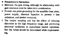
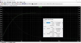
There should be no obvious phase shift introduced by the amp itself across the full audio band and beyond. This shows the phase shift at 50kHz which is minimal.
Don't include the input filter in this because that will of course add substantial phase shift at both HF and LF (LF due to both coupling cap and feedback return cap).
With and without input filter at 50kHz and an overall plot of phase response with filter. This is at 2.83 vrms output with levels for test normalised to overlay input and output.
Attachments
If you look at the original article, the spec was 100W@8R and 150W@4R max, presumably resistive load. Modern speakers are often 4R or less and seriously reactive with it.
As the design lacks anything except fuse protection, using a supply of +/-40V is safer. The Maplin design belongs to a time when Mosfets were being marketed as almost indestructible thanks to positive temperature coefficient and ignoring the peak die temperature
As the design lacks anything except fuse protection, using a supply of +/-40V is safer. The Maplin design belongs to a time when Mosfets were being marketed as almost indestructible thanks to positive temperature coefficient and ignoring the peak die temperature
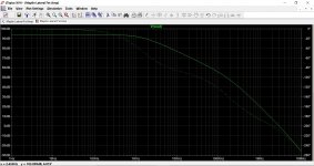
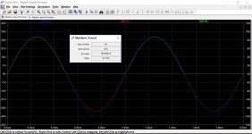
Here is the open loop response although it doesn't tell much about the reality of hanging a reactive load on the end. A real world build would be quite different in absolute values. The simulation also lacks an output inductor which would normally be required for guaranteed stability.
Attachments
There were two versions of the Maplin design
This is the second HiFi version from 1990
http://www.americanradiohistory.com/Archive-Maplin-Elrectronics/Maplin-Electronics-1990-12-01.pdf
Thanks, I don't recall seeing that before.
Wonder why the unbalanced input stage was left with R2 at 47k. Although the DC offset will depend on device matching to some extent I still can't see the logic in having 33k on one side and 47k on the other.
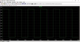
The original Hitachi databook and app notes for Lateral MOSFETs (HLN600) shows the attached image as "fabrication precautions" for folks that build the circuit.
For folks that want to use the design and just want to und.erstand Lateral MOSFETs in general, HLN600 is recommended reading, so is worth seeking out.
It also includes a (presumably recommended) layout.
And lots of comments about the choice of transistors used in the differential VAS, which is viewed as important
Here is a readable link but not the highest quality:
https://www.diybanter.com/attachmen...mosfet_appnote-pdf-hitachi_mosfet_appnote-pdf
mlloyd1
....The simulation also lacks an output inductor which would normally be required for guaranteed stability.
Attachments
Last edited:
Thanks. That plot looks almost too perfect. The real circuit has different transistors and parasitics so this is not accurate but nothing there to set off alarm bells. The amp appears to have about 60dB max loop gain.Here is the open loop response although it doesn't tell much about the reality of hanging a reactive load on the end. A real world build would be quite different in absolute values. The simulation also lacks an output inductor which would normally be required for guaranteed stability.
How often do you expect to change the fuses? How about in-line fuse holders at the psu caps? It is more important to keep the ground wires short than the pos and neg wires. Try to keep the pos and neg the same lengthThank you for the all time and effort you have put into this little project.
I said yesterday that running all of the wiring tightly bound in a loom wouldn't be a problem, and in my mind at the time it wasn't, until I looked at the unit today, I had totally forgotten one thing, The Fuses, I could run everything in a loom up to the fuses, but then there would be a break, and then continue to the PSU Caps, It would mean almost a complete rewire, or at least redressing, and at the same time add several inches to the lengths of the Ground wires, so not really sure what to do for the best at the moment, I know some people leave the fuses out and go directly to the caps, but I would prefer not to do that.
More than your supply rails.C8 and 10 - What minimum voltage rating would you recommend, I think I saw some polypropylene caps with a DC rating of 100v DC, so not too big physically.
The performance will be sensitive to the quality of parts in the feedback path.All Electrolytic caps have been replaced, but as you point out there are probably better devices other than the standard ones I have fitted.
So 470ohm trimmers will be fine.Regarding the Trim pot, The Supply Rails are +/- 50v from a 35v - 0 - 35v 300va Toroid.
Good.C2, RS have the WIMA FPK2 - 470pf with a lead pitch of 5mm, so that would probably fit
Nice.I like the idea of cutting the tracks and fitting SMD components for the Gate Resistors, I have a bunch of Zero Ohm Links for another project I'm about to start, which would be neater than wire links.
I should have been more clear. I meant the closed loop phase margin. Easy to simulate but tricky to measure on the bench.C5 & C6, The circuit as is, the output is slightly out of phase with the input but I didn't make a note of how much, probably somewhere around 15 - 20 degrees at a very rough guess.
Mooly pointed out that R2 has a different value to R7. I missed this. Normally they should be the same so that the LTP base currents, which should be the same if the thing is in balance, cause the same voltage drop across them. Otherwise the output dc offset will be further from zero. But it depends on other components being in balance (matched betas and same Ic). So it may not be a problem in the actual circuit. If your dc offsets are positive, like more than 20mV, you might want to change R2 to 33k.
I tend to agree. The FETS are only 7A devices and with worst case 100V across them they can only sustain 0.9A or a 10ms 3A pulse. At 50V then can do 2A continuous and 6A pulsed. But thats at 25C junction...the limits fall as the FET warms up.If you look at the original article, the spec was 100W@8R and 150W@4R max, presumably resistive load. Modern speakers are often 4R or less and seriously reactive with it.
As the design lacks anything except fuse protection, using a supply of +/-40V is safer. The Maplin design belongs to a time when Mosfets were being marketed as almost indestructible thanks to positive temperature coefficient and ignoring the peak die temperature
Even driving an 8 ohm resistor at near 50V when FETs are cold will get very close to the safe operating area envelope. A loudspeaker's impedance varies and some drop to 2 ohms at times.
So I'd also be inclined to use a 30-0-30 transformer and 42V rails to be safer. Although that isn't exactly "safe". But your are more likely to get away with it. A big expense unfortunately. 42V rails should give 80W to 90W average into 8 ohms.
Last edited:
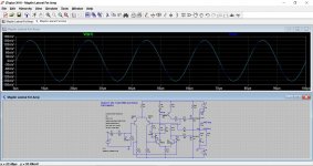
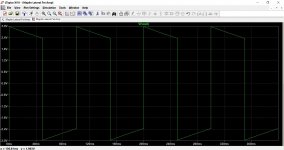
This shows 150 wrms (approx. 25vrms output voltage into 4 ohms) and it can be clearly seen that the FET's are over driven. Drain current is near 8.8A peak.
I wonder how the transconductance of the real FET's would hold up. In this sim there is 10 volts across gate/source to deliver that current.
I wonder how the transconductance of the real FET's would hold up. In this sim there is 10 volts across gate/source to deliver that current.
Attachments
How often do you expect to change the fuses? How about in-line fuse holders at the psu caps? It is more important to keep the ground wires short than the pos and neg wires. Try to keep the pos and neg the same length.
Looks as though a re-layout is in order, In Line Fuse holders are a good idea, I'll have a look and see if I can find some that would take the gauge of wire I'm using, possibly something in the Automotive line.
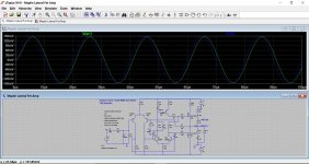
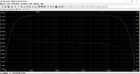
There should be no obvious phase shift introduced by the amp itself across the full audio band and beyond. This shows the phase shift at 50kHz which is minimal.
Don't include the input filter in this because that will of course add substantial phase shift at both HF and LF (LF due to both coupling cap and feedback return cap).
With and without input filter at 50kHz and an overall plot of phase response with filter. This is at 2.83 vrms output with levels for test normalised to overlay input and output.
Thank you for the time you have put into doing these simulations, Very interesting to see how things work under different scenario's without risking a real unit.
Regarding the phase shift, I think at the time I was looking at a square wave in 10 to 100Hz region, so that would explain things, also at around 100hz and below the top and bottom of the square wave slope off, much like what you would expect to see when you turn a Bass Control down, I think the Maplin article mentions a roll off at around 100hz, so that's probably what I was seeing.
I tend to agree. The FETS are only 7A devices and with worst case 100V across them they can only sustain 0.9A or a 10ms 3A pulse. At 50V then can do 2A continuous and 6A pulsed. But thats at 25C junction...the limits fall as the FET warms up.
Even driving an 8 ohm resistor at near 50V when FETs are cold will get very close to the safe operating area envelope. A loudspeaker's impedance varies and some drop to 2 ohms at times.
Aha, so this would possibly explain why my O/P Transistors reach 61°C when driving a continuous sine wave of 25v Pk-Pk into a 7.5 ohm dummy load? and just that's the Case Temp, and to quote "mchambins" Quote "Transistor junction temperature is not transistor case temperature".
Actually, thats how this entire thread started.
")
That would be easier with the existing layouts.The dual die FET's would be a good option, possible with a slight increase in driver stage current to allow for the increase capacitive loading..
These days there is no advantage to single sided PCBs, with the soldering reliability problems they always have. A dual sided PCB would make a sensible and stable layout much easier to achieve
- Status
- This old topic is closed. If you want to reopen this topic, contact a moderator using the "Report Post" button.
- Home
- Amplifiers
- Solid State
- Any Maplin MosFet Amp Guru's on here?