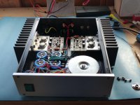
Just finished refurbing my original 1980's Maplin MosFet Amps, 2SK133 - 2SB48, Fitted in new case etc....
Before installing them in their final resting place, I ran them up on a +/- 15v supply, just to make sure they were working ok.
Today came the day to run them up on the full supply, after setting the Bias Current (50ma) is the figure I have for these.
All checked out ok, and with about 10mv dc on one amp and 14 - 15mv dc on the other.
My initial goal was to run them up slowly in 5v pk-pk steps, I only got to 15v pk-pk when I realised the OP Transistors were very hot, and by that I mean holding a pinky on one of the transistors started to get very uncomfortable after about 10 seconds.
I thought I had provided adequate heatsinking, after all, I'm using the original heatsinks I used from when first built them many years ago, and they gave me years of trouble free operation, but at that time I didn't have access to a signal genny or scope, and being in my early 20's I just boxed them up and away we went.
In the configuration I now have, I have used the case side, which is 3mm thick, and the Amps are bolted through this to the Heatsink with 3 x 6mm bolts, which is 190mm long, by 80mm High, with 14 x 5mm thick 40mm Fins, couple this with the side panels which are 90mm High and 290mm long / deep, and that's quite a lot of metal to heat up.
The one thing I did notice, is that over the years the Heatsinks have bowed very slightly, so there is a very small gap at the front and rear between the heatsink and case side.
I couldn't find my Thermocouple's at the time to see exactly what temperature the transistors got to, but I have found them now, so will take some readings tomorrow, ummm Later today now !!
As the heading implies, is there anyone using one or a pair of these amps at the moment, or carried out tests with a sine wave, and noticed they generally run pretty hot, or am I going to have to rethink my mounting method, and possibly drill and tap some more holes at the ends of the heatsinks which I have just had sand blasted and resprayed
Its not a heatsink its a mounting bracket to bolt to a heatsink.
Yes Sorry, The Amplifier Mounting Bracket is bolted through the side panel to the heatsink, I'll try and put a photo up later.
The Bias is set to 50ma with No Output Load attached, A temporary 250ma Fuse in the Negative Rail, and the Bias set with a meter across the positive rail fuse (Fuse Removed).
I seem to recall these amps running very cool, and maybe they will with normal use, and not a continuous sine wave.
Last edited:
they generally run pretty hot, or am I going to have to rethink my mounting method
All thermal transfer surfaces should be very flat, and preferably machined.
The metal surface should be anodized, not painted, for good transfer.
All thermal transfer surfaces should be very flat, and preferably machined.
The metal surface should be anodized, not painted, for good transfer.
The rear (Contact Side) of the H/S is not painted, but the side panel is anodized, Maybe that's where my problem lies !
Edit, Maybe not Anodized, but a Black Brushed Aluminium surface, it does have a good coating of thermal paste between the H/S and Side Panel, not ideal I know.
Last edited:
I turned mine on for a bout 15 minutes without extra heat sink and it is cold.
However I don't set up my amp as Maplin recommend.
I applied sine wave and monitored the output with speaker connected.
I turned up trimmer until crossover distortion went and it sounds fine.
If I remember right the correct setting for these lateral mosfets is 100mA bias current. Remove positive rail fuse and put a current meter across the fuse terminals and set to trimmer to give 100mA. Connect to fuse terminal using croc clip leads so you don't have to hold them on. If the rail becomes disconnected you can damage the speaker and amp.
Last edited:
An externally hosted image should be here but it was not working when we last tested it.
I turned mine on for a bout 15 minutes without extra heat sink and it is cold.
However I don't set up my amp as Maplin recommend.
I applied sine wave and monitored the output with speaker connected.
I turned up trimmer until crossover distortion went and it sounds fine.
If I remember right the correct setting for these lateral mosfets is 100mA bias current. Remove positive rail fuse and put a current meter across the fuse terminals and set to trimmer to give 100mA. Connect to fuse terminal using croc clip leads so you don't have to hold them on. If the rail becomes disconnected you can damage the speaker and amp.
The 50ma Bias was in the original documentation, but I suppose might have changed over the years, or possibly for the 2SK135 and 2SB50 variants.
I was feeding mine into a 7.5 ohm 100w Dummy Load, No crossover distortion present at 50ma Bias.
I found the datasheet.
An externally hosted image should be here but it was not working when we last tested it.
I think my best bet would be to unbolt one of the amps from the side panel arrangement, and bolt it directly to the Heatsink, and see if it runs cooler, if that's the case, then I will have to cut some slots in the side panel to allow the amp mounting brackets to pass through directly to the H/S.
I found the datasheet.
An externally hosted image should be here but it was not working when we last tested it.
I think that's the same or similar to the one I have, 50ma Bias.
I redesigned the Maplin mosfet amplifier for myself.
I added constant current source on front end.
I made the current mirror into a 2 transistor current mirror.
I decoupled the front end to isolate it from the output power supply.
I also increased the capacitance on the second LTP to increase stability.
The original Maplin amp was a bit skittish and oscillated if given half a chance. Mine suffered from hum even with input shorted.
An externally hosted image should be here but it was not working when we last tested it.
An externally hosted image should be here but it was not working when we last tested it.
Last edited:
Been on 25 minutes now and seems to be settling around 42 degree C.
Is that at idle, i.e. no input signal? Mine just get slightly warm in that state.
Oscillated why? I ran mine with 100% feedback as an experiment and it was stable. Mooly did a simulation with 100% feedback when I told him and got the same result
The capacitors were made so the amp was as fast as possible without oscillating. If I touch the output transistors the amp oscillates and draws lots of current.
Did Mooly find models for those old Hitachi mosfets? I struggled and gave up. Good job - you've been vindicated! Now don't do it again.Oscillated why? I ran mine with 100% feedback as an experiment and it was stable. Mooly did a simulation with 100% feedback when I told him and got the same result

- Status
- This old topic is closed. If you want to reopen this topic, contact a moderator using the "Report Post" button.
- Home
- Amplifiers
- Solid State
- Any Maplin MosFet Amp Guru's on here?