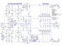
The first thing I see is a front end running at rail voltage. Usually this leads to poor PSRR because there is nothing to filter out ripple on the rails. The amount of parts you just saved need to all be put into the supply to try to reduce ripple, which leads to more supply sag and if you plan to share supplies between channels, more cross talk.
That design is very similar to an old Hitachi lateral mosfet datasheet design.
Maplin used it in their mosfet amplifier.
I built one and it suffered from hum with input shorted.
So I set about improving it.
1/ Add CCS to front end instead of just a resistor.
2/ Turned current mirror into 2 transistor version.
3/ Add decoupling to front end to reduce hum and improve PSRR.
4/ Increased slightly second LTP feedback capacitors to make more stable.
The results were very good.
Thanks for sharing your experience. Since I have a couple of populated PCBs for this amplifier I may give that a try first (as monoblocks) with some of your tweaks.
i suggest 2 channels of this amplifier in post 341. i have made it before and its quite good. you can read the while thread for more information.
MOSFET Amplifier IRFP240/IRFP9240
Also, thanks for pointing me to this amp. I was not aware of it. The simplicity of the design is attractive.
Consider building a 4-channel amplifier optimized for stereo Bi-amped speakers. Each left/right side of heatshinks includes one high wattage Class-AB for the woofer, and one modest wattage Class-AB for the midrange and tweeter which use a local passive crossover.
You can use the same SlewMaster driver PCB for all four channels, and just change the number of outputs transistors plus adjust the bias.
==========
The +/- 15V DC power supply used for the servo opamps can support more complex protetion ciricuits. This power supply can also run an analog Bi-Amp crossover PCB with a few opamps which can implement LR4 plus Linkwitz Transform bass boost. .. about 8-opamps total .. 4/channel. Using a socket for the passive crossover components would allow easy swap to different speakers.
Winter Is Coming.
Attachments
Make a monophonic "monoblok" bridged amplifier. >520 watts into 8 ohms, bridged. It will possess adequate safety margin for a 1KVA transformer including soft start and DC blocking. Do the Bob Cordell stunt of having 2 bridge rectifiers and 2 filter capacitor assemblies; one for the front end (with very small current loading) and another for the output stages (with enormous current load). Get another 1.5V to 2.5V of clipping margin at extremely low cost.
Make a monophonic "monoblok" bridged amplifier. >520 watts into 8 ohms, bridged. It will possess adequate safety margin for a 1KVA transformer including soft start and DC blocking. Do the Bob Cordell stunt of having 2 bridge rectifiers and 2 filter capacitor assemblies; one for the front end (with very small current loading) and another for the output stages (with enormous current load). Get another 1.5V to 2.5V of clipping margin at extremely low cost.
I would prefer to have the ability to drive 4 ohms loads...
So far the Slewmaster or, for something a bit simpler, the Apex HV23 seem like good options. I would need to do a layout for the HV23 unless someone has a PCB design I can use.
Last edited:
I will have some Slewmaster boards made since that design seems like a winner all around. I will order:
- 5 pair OPS board (using 2oz Cu)
- Kypton ND IPS board
Hmmmmm.... at every turn there seems to be an issue. I have no clue how to match transistors.
Maybe I should be asking this kind of question:
Which of the IPSs for the Slewmaster OPS (5-pair version) is easiest to build and tune, doesn't require any special parts or parts matching or circuit/PCB mods, and for which Gerber files are available or PCBs for sale???
I want to build a high performance amp but don't want to invest a lifetime into that endeavor. I also don't want to dread screwing up the build so much that I never fire it up.
Last edited:
Transistor matching should be done on just about any input dedign for best performance. It's quite easy to do. A cheap EBay transistor tester will get you close enough. Use On Semi transistors on the input end. They match pretty good usually.
I assume that I should match transistor gain (Hfe), right? How "close" is a good match?
I do have one of those ATmega based component testers that can measure transistor Hfe.
The ATmega is OK for batching components into similar grades.
But when you use it you will find it reports just a few different values with many members in each value that "appear" identical to their peers.
Matching when required is best done at the operating current they will see in the final circuit.
This rules out the ATmega and all the hFE testers built into DMMs.
I reckon you should be matching Vbe and hFE and that you do this when the transistors are at the SAME Tj.
I believe this can only be done in a pair jig where you thermally couple the nearly matched devices and find the few that really do pass the same current and thus dissipate the same power to give the same Tj.
Some of these pair jigs are discussed in the Forum.
Ya Know....
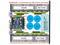
If you put a 4" x 5" MiniDSP 2x4HD PCB into the 4-channel(2*Big + 2*Modest) amplifier chassis I described earlier, you could get great sound from a variety of speakers with just a program download.
Mounting the toroidal transformer to the front panel helps open the chassis for both a DC_Servo and protection PCB with +/- 12V power supply stacked below the MiniDSP.
MiniDSP 2x4HD only requires 12V @300ma supply(wall wart supplied).
You could design the basic chassis to support building in phases:
1) Two high wattage channels, the future Woofer amplifiers(4-5 output pairs). I favor VFA circuits with all analog opamp/comparator protection ckts.
2) BASIC Protection PCB with +/- 12V supply
3) Two modest wattage channels, the future mid-tweet amplifiers(2-3 output pairs).
3) MiniDSP.
4) Expand protection functionality
Attachments
Ya Know....
If you put a 4" x 5" MiniDSP 2x4HD PCB into the 4-channel(2*Big + 2*Modest) amplifier chassis I described earlier, you could get great sound from a variety of speakers with just a program download.
Mounting the toroidal transformer to the front panel helps open the chassis for both a DC_Servo and protection PCB with +/- 12V power supply stacked below the MiniDSP.
MiniDSP 2x4HD only requires 12V @300ma supply(wall wart supplied).
You could design the basic chassis to support building in phases:
1) Two high wattage channels, the future Woofer amplifiers(4-5 output pairs). I favor VFA circuits with all analog opamp/comparator protection ckts.
2) BASIC Protection PCB with +/- 12V supply
3) Two modest wattage channels, the future mid-tweet amplifiers(2-3 output pairs).
3) MiniDSP.
4) Expand protection functionality
This is not a bad idea, though my days of using the miniDSP products are more or less behind me.
I happen to have a couple of (empty) 3U rackmount server chassis. A small SBC like a Raspberry Pi could fit where the drives would typically mount in the chassis. That leaves a lot of room left over for amplifier parts. I was planning to build up some 4 or 6 channel class-D amps with SMPS in the chassis in the near future anyway (that is a different project alltogether) and I might try to include a Raspberry Pi and two stereo ES9023 DAC boards just to see how that all works out. I can always remove them if there are issues with interference or what not.
Charlie, you could still use this multi-phase build strategy with your freeDSP design, even with 2-input / 6-output.This is not a bad idea, though my days of using the miniDSP products are more or less behind me.
Heatsink USA store on diyAudio has a 10.08" wide heatsink for $6.65/in height. A 9" high, $60 heatsink can support 4-6 pairs of outputs. A 9" high chassis allows mounting the toroidal transformer to the front panel. I favor using a powerful PC with measurement tools and advanced graphics to program the DSP board for several different speakers, instead of using a mini-LCD and mini-functionality PIC for setup.
Attachments
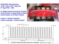
Charlie, you could still use this multi-phase build strategy with your freeDSP design, even with 2-input / 6-output.
Heatsink USA store on diyAudio has a 10.08" wide heatsink for $6.65/in height. A 9" high, $60 heatsink can support 4-6 pairs of outputs. A 9" high chassis allows mounting the toroidal transformer to the front panel. I favor using a powerful PC with measurement tools and advanced graphics to program the DSP board for several different speakers, instead of using a mini-LCD and mini-functionality PIC for setup.
That's funny. You are not the first person to think that the FreeDSP platform is my own. I only started the thread about it after finding it on the web, since it is a nice open source alternative to miniDSP (or was at the time). I really don't have anything to do with it, honest!
")
I do have some nice large heatsinks from HeatSinkUSA (in that width and the 8" version). I have some plans for them for Class AB amps that I will build in the future. But at this time it looks like I will be going with 2-channel Class-D amplification using amp boards designed by a forum member. I might build a more sophisticated amp like the Slewmonster in the future, but I just have too much on my plate currently to take that on at this time. The class-D amp boards are pre-built and tested so I only need to assemble the PS and wire everything together. THAT, I have time for, just barely.
- Status
- This old topic is closed. If you want to reopen this topic, contact a moderator using the "Report Post" button.
- Home
- Amplifiers
- Solid State
- 1kVA 50+50V toroid... what amp to build?