Enormously surprised by the speed and with the technicality that xrk971 has built it. Much more proudly I feel that we are already two who have been pleasantly satisfied by this amplifier.
I can not find words of thanks for the trust you have placed in me.
I am convinced that this amplifier will not disappoint whoever builds it.
Regarding C1, I must say that everyone has the freedom to install the one that seems most convenient to their needs. In my opinion, I have dimensioned that great value for the maintenance of low levels of THD at low frequency and to maintain similar energy profiles corresponding to a low frequency damped signal (signal that could correspond to a kick of a bass drum, for example) . Comparing between the two values for C1 (between 10 uF and 4700 uF, for example), we see that the envelope profile of the decreasing amplitude of the damped signal changes. But what is most disturbed is the envelope of the instantaneous energy that reaches the base terminal of the BC560C. The envelope takes on an entirely different profile. As the signal frequency increases, the profile tends to resemble that of the original signal.


That is my criterion for selecting the value of C1. I totally respect the criteria of whoever wants to adopt another minor value.
To Hugh and others, again thank you very much for your wise reflections.
Best regards
I can not find words of thanks for the trust you have placed in me.
I am convinced that this amplifier will not disappoint whoever builds it.
Regarding C1, I must say that everyone has the freedom to install the one that seems most convenient to their needs. In my opinion, I have dimensioned that great value for the maintenance of low levels of THD at low frequency and to maintain similar energy profiles corresponding to a low frequency damped signal (signal that could correspond to a kick of a bass drum, for example) . Comparing between the two values for C1 (between 10 uF and 4700 uF, for example), we see that the envelope profile of the decreasing amplitude of the damped signal changes. But what is most disturbed is the envelope of the instantaneous energy that reaches the base terminal of the BC560C. The envelope takes on an entirely different profile. As the signal frequency increases, the profile tends to resemble that of the original signal.
That is my criterion for selecting the value of C1. I totally respect the criteria of whoever wants to adopt another minor value.
To Hugh and others, again thank you very much for your wise reflections.
Best regards
Last edited:
As soon as I get home I'll post a pdf and gerber files. I'll also add 5mm lead spacing for the three caps.

Hi Diegomj,
I am glad the circuit worked the first time. That's always a good feeling. One of my few amps that I fired up without a protection safety resistor or safety light bulb tester. lucky this time.
On your profile above you are comparing power vs volts. Can you plot both as power? I believe they should be similar assuming the base of the transistor doesn't have a low impedance.
I am glad the circuit worked the first time. That's always a good feeling. One of my few amps that I fired up without a protection safety resistor or safety light bulb tester.
lucky this time. On your profile above you are comparing power vs volts. Can you plot both as power? I believe they should be similar assuming the base of the transistor doesn't have a low impedance.
I'm so glad you understood the difference.
The second graph is well revealing of the difference in the envelope, between employing a low capacitor value for signal passage and employing a high capacitor value for the same function.
Electrically, there are differences. I think, psychoacustically could be perceived as well.
Best regards
The second graph is well revealing of the difference in the envelope, between employing a low capacitor value for signal passage and employing a high capacitor value for the same function.
Electrically, there are differences. I think, psychoacustically could be perceived as well
.Best regards
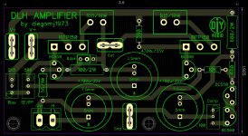
Well done all of you guys that contributed, the turn-around was extreme and the outcome exemplary. I will be putting it together in the next few days as I have become a low power class A nut. Unfortunately I cannot work at the pace of XRK971 but I will give it my best shot. Thanks for sharing diegomj1973, XRK971 thanks for confirming and Ripcord, the PCB is so elegantly simple.
Last edited:
Member
Joined 2009
Paid Member
Member
Joined 2009
Paid Member
Anybody going to try it n an all-BJT version?
I have already tried, but it seems that the best results are obtained with null or extreme low currents towards the output transistors. Although not entirely to my liking, you can try to implement it with Darlingtons. The best results I have obtained with mosfets.
I've tried building the NTP with mosfets, too, but it subtracts more efficiency than actual scheme.
regards
Last edited:
This amp is so simple you guys could easily P2P this on veroboard. I might build the second channel tonight. Thinking about running this at 24v rails and 1.2amps similar to Pass amps as I have that PSU trafo already. Although buying another 100w 15vac trafo for a dual mono setup would be pretty cool too. I need a big heatsink though. The big case I have is a Dissipante 3U with the Pass M2 that currently hums with no solution in sight might be a candidate. Been working for months on the hum issue and it's due to mains EMI pickup from signal transformer.
- Home
- Amplifiers
- Solid State
- DLH Amplifier: The trilogy with PLH and JLH amps