The composite using either a gain stage, or a Current Buffer for the second stage usually offers increased performance.
W.Jung has written extensively on this. Our Member Tomchr has produced such a composite and to date his achieved performance is way above what any plain Jane 3886 could achieve.
It would be interesting to analyze how it would be implemented in my circuit and try to verify if it improves the current parameters, see to what degree it could improve them and if it justifies more circuital complication.
Welcome who wants to contribute ideas and in this way to be able to improve it.
regards
> The circuit was first described by Christopher Rush in 1964.
I have it, uncreditied, in a book from 1966?
I re-invented it a decade ago except as two inputs (put a resistor between the emitters to define gain). It makes a differential input where 2nd does not cancel. THD is tiny for low gain but if you open it up as a mike-amp you get usual low-NFB BJT curvature.
> nothing is new under the sun
The ancients are always stealing our inventions. Especially in audio.
Yes, i missed thatRegards
 .You made your point (or not
  )
)The schematic i posted before has the same problem
The ground symbol on the most negative side has to go.Mona
Last edited:
Something similar, also nice:
http://www.andiha.no/articles/audio/nostalgia/nostalgia.pdf
from this site:
Audio
http://www.andiha.no/articles/audio/nostalgia/nostalgia.pdf
from this site:
Audio
The ancients are always stealing our inventions.
A creature with a "rotary engine" Flagellum - Wikipedia
Here the circuit of the NAD 3020. It is a real shame that they have not taken advantage of the collector terminal of the BC559 (corresponding to the series LTP) . In that way, perhaps they could have used only four transistors.
The only thing in the NAD 3020 that resembles to my circuit is that it uses series LTP, too. In my humble opinion, the full potential of that input circuit has been wasted.
Regards
The only thing in the NAD 3020 that resembles to my circuit is that it uses series LTP, too. In my humble opinion, the full potential of that input circuit has been wasted.
Regards
Attachments
Something similar, also nice:
http://www.andiha.no/articles/audio/nostalgia/nostalgia.pdf
from this site:
Audio
Thank you juma. Nostalgia is three stages. My design is only two stages
.Similarities: both eliminate the undesirable output capacitor. But in my design, the capacitor of the feedback network is also eliminated, improving to some extent the IMD
.Regards

Goodness guys, give the man a little space, he is sharing an idea that could be a nice sounding amplifier, whether it existed in the stone age is totally irrelevant.
The DIYaudio community would do their level best to ridicule another member for sharing what he believes is an original idea.
Diegomj1973 post your idea in a forum that would appreciate it.
I simmed it, and it looks very promising, I am keen to hear it too. To me your idea is original in its implementation.
Last edited:
Nico, where did you see "ridicule" ?
Of course it's a nice project and the contribution is appreciated, but prior art is certainly not irrelevant, especially when it comes to very old and popular design that set the milestone in its own time...
The title of this thread itself mentions JLH and PLH and I just quoted another successful implementation of the same idea, that is worth mentioning in the context.
Last edited:
Not talking about you Juma. Prior art exists for almost everything, but it seems like it is rubbed in to ensure there is no misleading claims made. Just the phrase "my design or idea" invites immediate reaction of who had done it and how many times. Anyway, the differential is nothing new but the way he used it as diver/phase splitter is quite enlightening something that does not immediately spring to mind, and I assure you I have been around a long, long time.
Last edited:
Do not feel offended, I did not want to offend anyone. I simply decided to share with the forum community something that I could design and, humbly, put together to give testimony of how it works.
Like every designer, we put our imprint on what we design, but we always rely on something already preexisting. This is how the world works. Like any circuit, what I designed has virtues as well as failures. Nobody designs infallible circuits. From now on, someone else can put your imprint to improve it. In this way, we will continue to move the world. I invite you to help me.
I thank you once again for belonging to this prestigious forum and being surrounded by people of extraordinary ability like yours .
.
Regards
Like every designer, we put our imprint on what we design, but we always rely on something already preexisting. This is how the world works. Like any circuit, what I designed has virtues as well as failures. Nobody designs infallible circuits. From now on, someone else can put your imprint to improve it. In this way, we will continue to move the world. I invite you to help me.
I thank you once again for belonging to this prestigious forum and being surrounded by people of extraordinary ability like yours
.Regards
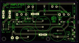
After having built the ESP P113 to use for my small bench speakers, and loving the sound by the way, I'm drawn to low power amps with nice performance. I put together a pcb for the DHL amp and was hoping someone could look it over. Thanks.
Attachments
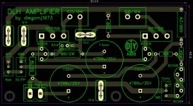
Sorry, I like this one better.
Exceptional work!!!. It only remains to build it and verify that everything works as it should. Once again, thank you very much for your great effort.
Remember that it is an amplifier that operates quite hot. Mosfets should be mounted on a generous heat sink.
All my respects
Last edited:
The compensation circuit schematic on right is not equivalent to the one on the main circuit on left. R3 does not go to ground in the one on left but does on the right one. And 390R does not go to ground on left but negative rail.
Which one is correct? I assume the one on left since made by OP.
Also why is C1 4700uF? For sufficient bass extension down to 1.6Hz for 10k R1 only a small 10uF is needed. Unless the impedance through the base of the BC560 is like in the single ohms?
Last edited:
The DLH Sings!
I had some time and am a sucker for simple Class A amps, especially quasi amps with singleton input stage.
So using a Sharpie marker, I laid out the circuit on el cheapo copper faced phenolic board (using the schematic from Post #25, schematic on the left, not the revised compensation):

After a quick etch in HCl/H2O2 for 20 minutes, I built it up. A couple of mods: I added 220R gate stoppers in front of the MOSFET gates, and switched to a 10uF 35v Silmic II for C1 (could not see the sense of a 4700uF there). I am also using readily available "10,000uF 25v" caps (measure at 6000uF) for the other two caps. Using a 88pF NP0 cap soldered from 3 SMT caps. Also, using IRFP240 vs 150's. So here is the built up amp:


Now testing the amp with a linear PSU nominal 15VAC (20VDC rails no load) from 100VA trafo. Under load rails are 15.5v. Bias is very adjustable - came on at 3.8amps and I adjusted down to 1.8amps. Offset adjusts nicely with good range and resolution. Offset affects bias and vice versa so it is an iterative process. I do not have a sufficiently large heatsink at present so testing for limited time with smaller ones here:

Then hooked up my XKi speaker with dual PA130-8's in 4ohm nominal (95dB at 2.83v) and used my iPhone as source. It sings! Sounds really nice - good tonal balance and has some good foot tapping dynamics and rythm. With the CRC Class A PSU from GB led by Prasi, and a cap array, the amp is dead silent even with 95dB sensitive speakers (no hum or audible hiss). So only listening in mono, but this amp is nice and deserves a second channel for stereo.

The schematic is now verified to work and the amp sounds very nice. Great job Diegomj1973 - thanks!

Cheers,
X
P.S., I did not get to play with the trimpot that adjusts between SE and PP yet - looking forward to that. Adjustable harmonic profile is very cool to have.
I had some time and am a sucker for simple Class A amps, especially quasi amps with singleton input stage.
So using a Sharpie marker, I laid out the circuit on el cheapo copper faced phenolic board (using the schematic from Post #25, schematic on the left, not the revised compensation):
After a quick etch in HCl/H2O2 for 20 minutes, I built it up. A couple of mods: I added 220R gate stoppers in front of the MOSFET gates, and switched to a 10uF 35v Silmic II for C1 (could not see the sense of a 4700uF there). I am also using readily available "10,000uF 25v" caps (measure at 6000uF) for the other two caps. Using a 88pF NP0 cap soldered from 3 SMT caps. Also, using IRFP240 vs 150's. So here is the built up amp:
Now testing the amp with a linear PSU nominal 15VAC (20VDC rails no load) from 100VA trafo. Under load rails are 15.5v. Bias is very adjustable - came on at 3.8amps and I adjusted down to 1.8amps. Offset adjusts nicely with good range and resolution. Offset affects bias and vice versa so it is an iterative process. I do not have a sufficiently large heatsink at present so testing for limited time with smaller ones here:
Then hooked up my XKi speaker with dual PA130-8's in 4ohm nominal (95dB at 2.83v) and used my iPhone as source. It sings! Sounds really nice - good tonal balance and has some good foot tapping dynamics and rythm. With the CRC Class A PSU from GB led by Prasi, and a cap array, the amp is dead silent even with 95dB sensitive speakers (no hum or audible hiss). So only listening in mono, but this amp is nice and deserves a second channel for stereo.
The schematic is now verified to work and the amp sounds very nice. Great job Diegomj1973 - thanks!
Cheers,
X
P.S., I did not get to play with the trimpot that adjusts between SE and PP yet - looking forward to that. Adjustable harmonic profile is very cool to have.
Last edited:
Congratulations, X!!
Those caps are oversized because LTSpice then drives the noise floor down, revealing all the harmonics which ordinarily lie below the noise line, a quirk of the spice engine. Incredibly fast work, take a bow!
Diego,
This is a very good circuit, and now X has revealed that it sounds very good...... I know why this is happening; this has a monotonic linear reducing harmonic profile, and the ear sees this a 'natural'. Even if H2 were high at -66dB, such a profile would sound very good regardless high THD. As it happens, this has LOW THD as well.
Cheers,
Hugh
- Home
- Amplifiers
- Solid State
- DLH Amplifier: The trilogy with PLH and JLH amps