I recently replaced the original 1K wire-wound trimmers for DC offset in my Marantz 2325 with Bourns 3296Y. I was able to adjust offset with the old trimmers, but the new ones have no effect, at least at the speaker terminals - I can adjust to zero V at Pin 2 of the trimmer. One other thing I changed was a 33uF 6.3V tantalum that has one leg on a trace that links to Pin 2, replacing it with a Nichicon ES bipolar of the same value. Since the problem I'm experiencing is occurring in both channels and I replaced the tantalum on both sides, I'm wondering if using the bipolar ES cap rather than a polar Nichicon UKL may be the problem.
Last edited:
If you remove the cap, does it then work? If it does use the correct type of capacitor of refit the old ones.
If it makes no difference, check the variable resistor is actually varying on the correct pins.
Ok, I can try removing the cap. Yes, the resistor varies on the correct pins.
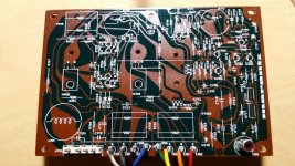
FWIW here's the board in question (not my photo). R713 is the trimmer and C703 is the cap in question.
Attachments
Measured at the output of the amp board, it's around 1V. That's also approximately what it is when measured at the speaker terminals.
High, but not devastatingly so. In post #1 you mention that it did adjust OK with the original parts fitted. This really does look like something has gone amiss with your fitting of the replacement parts.
If you post the circuit details showing the pot and how its wired then we might be able to advise what voltages you should actually be seeing in that area.
- Status
- This old topic is closed. If you want to reopen this topic, contact a moderator using the "Report Post" button.
- Home
- Amplifiers
- Solid State
- Bipolar cap in DC offset trimmer circuit