mcp said:In Slone's amp, cascode base is 4.4V from rails.
Regards
This is in line with Borlely 1981 modification of the DH-200 amp VAS and also in line with the theory of low memory distorsion. In my modified DH-200 I had to bias the cascode transistor at 5 V from rails to keep the THD at original specification. In one DH-200 prototype, I modified the cascode VAS to include a CFP si it became a constant power VAS! I have tested it with no oscillation but I had not the time to "hear" the result. Has someone already tried a constant power VAS in this forum?
hi again,
So far, we had a lot of interesting ideas to modify (and improve) the DH-200/220 amp. Thanks to everybody.
As I have indicated earlier, I present here mainly my mods that revealed an improvement (at least to my hears and some other peoples too). In the past, I tried several very different circuit configurations but it was almost impossible to get an appreciation of the circuit topologies (current mirror, cascode, follower, etc.)since the complete circuit of the amp did not compare at all with the other ones. Thus, I decided to experiment using a proven topology which was available easily, the DH-200/220. I do the mods consecutively so I can see the differences between each mod if they worth it or not (again, it is only my taste appreciation). I do not pretend that my conclusions are better or worse than others. And they are only based on a specific topology (fully complementary symetrical amp with output mosfet and all other bjt).
So far, I have mainly presented the well known front end regulated power supply (which I only got some e-mails requesting my regulator circuit used).
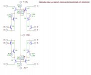
Next, I want to present the next significant mod, the "low memory distortion input stage. It consist of replacing the 4 input bjt with this attached circuit. It can be built using one Radio Shack universal pc board for the 2 channels. The resulting input module (1" x 2.5" for each channel) is installed as a daughter board on the main board.
I must say that I have heard details in the music which were not known to me before the mod.
Has anybody other diy used and appreciated this input arrangement?
Thanks
So far, we had a lot of interesting ideas to modify (and improve) the DH-200/220 amp. Thanks to everybody.
As I have indicated earlier, I present here mainly my mods that revealed an improvement (at least to my hears and some other peoples too). In the past, I tried several very different circuit configurations but it was almost impossible to get an appreciation of the circuit topologies (current mirror, cascode, follower, etc.)since the complete circuit of the amp did not compare at all with the other ones. Thus, I decided to experiment using a proven topology which was available easily, the DH-200/220. I do the mods consecutively so I can see the differences between each mod if they worth it or not (again, it is only my taste appreciation). I do not pretend that my conclusions are better or worse than others. And they are only based on a specific topology (fully complementary symetrical amp with output mosfet and all other bjt).
So far, I have mainly presented the well known front end regulated power supply (which I only got some e-mails requesting my regulator circuit used).
Next, I want to present the next significant mod, the "low memory distortion input stage. It consist of replacing the 4 input bjt with this attached circuit. It can be built using one Radio Shack universal pc board for the 2 channels. The resulting input module (1" x 2.5" for each channel) is installed as a daughter board on the main board.
I must say that I have heard details in the music which were not known to me before the mod.
Has anybody other diy used and appreciated this input arrangement?
Thanks
Attachments
I have repaired a lot of these, and done a few minor mods. I suggest several basic mods that add reliability only, since most of the the perfomance improvement mods I tried made it an oscillator, not an amplifier.
First, here is my list of the most common failures in these amps, with causes. The power switch fails, due to excessive inrush currents (see fix below). The output transistors do burn out, probably due to insufficient cooling coupled with oversized fuses on power. The input pairs go leaky due to overdriven inputs. When the outputs fail, they generally take out drivers and possibly inputs, as you would expect. That's what I see most often, so those are the areas I check first.
There is not a lot you can do to hugely improve the sound of this amp, in my opinion. Here are some small mods that preserve the essential character of the design while adding reliability.
The first mod is simply an NTC thermistor (5 ohm cold) on the AC power. This is needed to prevent the switch from failing due to high inrush current. On most of the amps I see, the power switch is toast and has to be replaced, but it will just fail again unless you do this mod. If you do nothing else, do this mod!
The second mod is a MOV across the transformer primary, in parallel with an X Cap of 0.047 400v. I also put the same value X cap across the rectifier bridge AC inputs. This removes switching transient noise on power on and off, and protects from line surges and noise.
The third mod concerns basic ground wiring. As designed, this amp does not have a single point star ground philosophy, but instead daisy chains ground. This is not wise practice from a noise standpoint. This amp uses a single ground wire to the speaker common, then to the board output power side. The input ground is provided via the output ground and a 2.2 ohm resistor. I don't like this practice, so I add a front-end ground return wire to star ground. In some cases this stops a hum or buzz. In addition, I tie the chassis ground lug on the output transistors terminal strip to the output ground, rather than depending on the chassis and screws to provide this ground. Finally, I use gold plated floating input jacks and tie the input signal return to chassis ground via 2.2 ohm resistors on both channels, breaking internal and external ground loops. I use a copper bus bar between both cap ground lugs to set up a star ground point midway between them. All grounds return to this point, although I use a second lug for the input grounds to avoid the high ground currents flowing to and from the center tap wire.
As designed, this amp sends the output to the fuse on the back panel, then back to the board and zobel net, then to the output binding post on the back panel. The intent was to include the fuse in the global feedback loop, in concept a good idea, but as implemented here not so good. This can result in radiated noise from the high level output signal to the input wiring or other points. I delete this feature, sendiing the output (twisted with output return lead) direct to the fuse then the binding post. This hopefully reduces one major source of distortion (per Self). You have to add a jumper on the board to bypass this fuse loop when you do this mod.
I sometimes rewire these to allow bridged operation, with a switch on the back panel to switch from mono to stereo. Use the instructions on the Hafler website for the DH220 bridging, but change the resistor to 2.2k for the DH200.
http://www.hafler.com/techsupport/pdf/DH-222_bridgeKitForDH-220.pdf
Some History: There are several versions of the driver board for this amp. The DH200 used a "PC6" driver board, which lacks certain features detailed below. The early versions of the DH 220 used the PC6, but switched to the "PC19" board in midlife. (I have DH220 manuals showing both versions.) These driver boards are very similar in topology, but have some minor differences that slightly improve sound in the later version. PC19C is preferred.
The very early (1978) versions of the PC6 used a mix of low voltage transistors on the input side (MPS8X99, BC456/556). These have higher beta but lower breakdown voltages. While the higher beta probably resulted in lower distortion and lower output offset voltage, they were less robust than the types used in the later PC19 (which used 2n5401/2N5551 except for the Vbe multiplier). I generally replace with the more robust parts when doing repairs.
Here is a list of the significant differences between the driver boards:
1. PC6 uses low voltage transistors in the front end, while PC19 uses the higher voltage parts.
2. The PC6 uses a bipolar electrolytic input cap, the PC 19 uses a mylar cap.
3. PC19 has an added output offset adjust pot.
4. The Darlington VAS uses a Baker clamp in the PC-19, to improve recovery from overload.
5. The output transistors have power bypassing on the DH-220, while those in the earlier DH200 do not. These are 0.1mf, 100v mylar caps to chassis ground. For stability, you should add these if they are not present.
6. Early PC6 boards used ceramic caps, which were changed to mylar or mica in later versions. In general, mylar bypasses were added across electrolytics in the later version.
All of these differences are evolutionary refinements and do not make cosmic differences in the sound, but are "nice to have". I suggest looking for the later driver boards if you are buying one of these.
I am very wary of major mods to this amp, because it seems to be on the verge of instability. I often see a very low level 60 MHz oscillation on the output of this amp, but it could me a measurement artifact. If you take out any of the low-pass filters on the input stage, it oscillates. If you remove the caps to ground on the VAS, it oscillates. Miller caps on the VAS don't seem to cure this. I think this is partly due to the physical layout and partly due to the high open loop gain of the circuit itself. Certainly the relatively long wires to the output transistor array are great antennas, right beneath the board. So, I pretty much leave the amp stock except for the mods discussed above.
I hope someday to lay out a new PC for this amp that uses flat pack lateral mosfets to eliminate the wiring to the output transistors which seems to contribute to the tendency to oscillate that I mentioned. To me that seems a better approach than hacking the present boards.
Slowhands
First, thank you for all your comments. As usual, you are very precise and clear. I agree mostly on everything you have indicated. In fact, I have already performed almost everything you have indicated. The re-routing of the "power" ground is imperative as it is also for the other ground connections.
However, I am not "wary" at all to modify this board. Maybe this is because I have always recovered from any of the numerous mods I have tried on this DH-200 driver board. It is true that when you remove a frequency compensation network of the amp it can oscillate but are any amplifier needing a compensation? The input cap is mainly to restrict an extremely fast input signal slew rate and this approach is well recognized and used. I confirm that no miller capacitors revealed to be usefull with any mods I have tried. The amount of overall feedback can be reduced a lot and still preserving a good stability. I actually use about 42 db which can be considered a low level feedback design.
Regarding the specific input stage mod described, the diy builder is not to wary at all since the stability of the amp will not be affected (if the same 2N5551 and 2N5401 are used for all input transistors). In fact, if a mod I suggest require an adjustment on the frequency networks I will indicate it.
Again, I try to present small very cheap mods that can be fun to do (at least it was for me). I have the layout of this input stage board using an universal cheap pcb for those "diyers" who are interested.
Thanks again for your valuable reply.
p.s. do you prefer my new look?
New Driver Boards
I've seen talk by at least two people on this thread about doing new driver board layouts I have probably one of the 1st DH200 ever made it has a blown left channel I would be very much interested in modernizing the driver boards and going to TO247 device's if any one come's up with a finalized board I would be very interested
I've seen talk by at least two people on this thread about doing new driver board layouts I have probably one of the 1st DH200 ever made it has a blown left channel I would be very much interested in modernizing the driver boards and going to TO247 device's if any one come's up with a finalized board I would be very interested
do some reading at borbely's site to get some more ideas for mods to these hafler amps:
http://www.borbelyaudio.com/index15.htm
http://www.borbelyaudio.com/index8.htm
http://www.borbelyaudio.com/index31.htm
source follower drivers on same pcb as outputs seems to help the "long wires to outputs" problem. Of course, it's probably even better to have everything on one PCB that's "properly designed".
and definately do a soft start mod of some sort!
good luck!
mlloyd1
Re: dh200/220 mods
MOV stands for Metal Oxide Semiconductor. These devices absorb and dissipate transients on the AC line above some chosen voltage. Because MOVs wear out if exposed to lots of transient energy over time, I use the slightly higher voltage versions. Here in the US (with a line voltage of 115VAC nominal) I use the 150v MOVs for longer life, instead of the commonly recommended 130v.
They must be placed after the line fuse, since when they wear out they short. I have never had one short, but it is a well publicized failure mechanism and must be considered. I think of them as replaceable fuses for overvoltage, rather than current. You will find them used on the input side of most PC power supplies, and as the surge absorber in the common "surge protected" multiple outlet AC line strips we all use.
X Caps are usually polyester dielectric caps that are rated for duty across the AC line. They are self healing and over-rated for voltage. Typically they are encapsulated in epoxy in a block shape or "box" shape. You need to have the manufacturers data sheet to verify that a cap is so rated.
I suspect many of the box caps in the surplus trade are X caps, especially if rated rated 250V (for 115V mains, or 400V for 220V mains). They are probably surplus from input filters on switching power supplies. If you are really cheap, you can extract these from the input filters of obsolete PC power supplies. The capacitance value is not critical, but the voltage rating is.
larryg said:SLOWHANDS, you mention an MOV across trans primary. What is a MOV? Also, an Xcap of .047-400v, in parallel with the MOV. What is a Xcap?
MOV stands for Metal Oxide Semiconductor. These devices absorb and dissipate transients on the AC line above some chosen voltage. Because MOVs wear out if exposed to lots of transient energy over time, I use the slightly higher voltage versions. Here in the US (with a line voltage of 115VAC nominal) I use the 150v MOVs for longer life, instead of the commonly recommended 130v.
They must be placed after the line fuse, since when they wear out they short. I have never had one short, but it is a well publicized failure mechanism and must be considered. I think of them as replaceable fuses for overvoltage, rather than current. You will find them used on the input side of most PC power supplies, and as the surge absorber in the common "surge protected" multiple outlet AC line strips we all use.
X Caps are usually polyester dielectric caps that are rated for duty across the AC line. They are self healing and over-rated for voltage. Typically they are encapsulated in epoxy in a block shape or "box" shape. You need to have the manufacturers data sheet to verify that a cap is so rated.
I suspect many of the box caps in the surplus trade are X caps, especially if rated rated 250V (for 115V mains, or 400V for 220V mains). They are probably surplus from input filters on switching power supplies. If you are really cheap, you can extract these from the input filters of obsolete PC power supplies. The capacitance value is not critical, but the voltage rating is.
Re: New Driver Boards
For my new driver board, the layout was almost completed but I decided since then to change the front end stage including more stable bias for the mosfet. Also, my intent is to NOT include the Mosfets on the driver board since I want to use this new driver board as a fit, form, function of the old Dh-200/220 stock driver board. Anyway, I do not have enough place to locate power output transistors on the driver board since my mods include several additional parts over the original design. Also, with the 470 ohms gate resistors, there is no real problem with the 4 to 6 inches wires between the board and the mosfets. My schematics is fully symetrical (based also on the original circuit topology) as mostly is the pcb layout done so far.
Once it will be finished, I will have to have it done, populate it, install it in one of my DH-200, perform a functional test, some kind of burn-in test and finally a listening test. So, it will keep me a while....
Thanks for your interest.
Spock
jhead said:I've seen talk by at least two people on this thread about doing new driver board layouts I have probably one of the 1st DH200 ever made it has a blown left channel I would be very much interested in modernizing the driver boards and going to TO247 device's if any one come's up with a finalized board I would be very interested
For my new driver board, the layout was almost completed but I decided since then to change the front end stage including more stable bias for the mosfet. Also, my intent is to NOT include the Mosfets on the driver board since I want to use this new driver board as a fit, form, function of the old Dh-200/220 stock driver board. Anyway, I do not have enough place to locate power output transistors on the driver board since my mods include several additional parts over the original design. Also, with the 470 ohms gate resistors, there is no real problem with the 4 to 6 inches wires between the board and the mosfets. My schematics is fully symetrical (based also on the original circuit topology) as mostly is the pcb layout done so far.
Once it will be finished, I will have to have it done, populate it, install it in one of my DH-200, perform a functional test, some kind of burn-in test and finally a listening test. So, it will keep me a while....
Thanks for your interest.
Spock
My approach to Hafler mods...
I've used Hafler amps for well over 2 decades, starting with building the kits back in the early 80s. While raising a family back then, I didn't really have time to do all the POOGE mods a la Audio Amateur's excellent articles over the years nor did I ever spend time doing what's been discussed here in this thread - small component changes looking for a good return on investment.
Instead, I took the more wholesale route using one of the available driver board replacement. I've now been through all 3 iterations of driver boards from Musical Concepts and each have offered improvements beyond what you'll ever be able to get by staying the original circuit topology.
See: http://www.musicalconcepts.com/mc_amp_mods.htm
These are fun and you can certainly have the amp up and running in short order. Many of the rewire items are taken care of with the installation, too.
I've since turned to tubes and have 2 of these now sitting on the shelf. Actually, that's not entire correct, one serves as backup for when I take down the tube amp for modifications - the kids now being out of the house and college!
Cheers,
David
thanh said:fab! i saw your post 22! Have you succeed in building that shematic?
Thanh,
Yes I Have succeeded!! and it works very well too. All the mods I indicate on this thread works prefectly. Every mods have been validated in 3 different DH-200 amps. For the input stage, it is installed for more than 1 year with no problem. I used 2 modified DH-200 amps in a bi-amp system.
Fab or Spock
balanced-inputs on the dh-200/220 series?
is this a waky idea?
maybe based on the application, it isn't. I want to get the benefits of balanced line operation on the input stage of my hafler.
I have some experience in the car audio area and balanced lines are quite popular, to reduce pickup-noise from nearby fields.
my amp might be located farther away from my preamp than I'd like. so I'm thinking of running balanced cables from the preamp to the amp - BUT - of course modifying both so that the input stage of the amp and the output of the preamp both 'speak' balanced.
I had an interesting idea - why not get a quality balanced line receiver and just install it INSIDE the hafler. there's a bit of room inside and it would save me having to put some clunky adapter box outside.
I like zapco stuff. they have something called 'symbilink' that runs the analog cables and the power in one mini-din cable. quite elegant, really. works well. you can get a balanced transmitter that takes in RCA and puts out this symbilink stuff. then a receiver box on the other side to do the inverse. the transmitter also 'transmits' power to the receiver box, so you really do use only 1 cable from Tx to Rx.
ok, with me so far? done laughing yet?
the zapco stuff can be found cheaply enough on ebay and is small enough that it -can- fit inside the hafler chassis. then I could take the mini din and panel mount it somehow and that would be my new amp input.
OR - before I get too far - is the hafler 200/220 input already floating?? so that really, I wouldn't even have to install a 'receiver' circuit? its been a while since I've opened my DH but I think the inputs are not floating (are they?)
comments on this whole idea?
Thanks
I've just found this thread and I'm really glad to see the good info about the Haflers. I've been using a pair of them for a long time and I just want to let you all know that there are others of us out here who appreciate the effort aimed at these good old amps.
Both of mine have the stereo/mono bridge boards in them and I set that up from the get-go to use a switch so I can quickly change them from bridged to stereo. That's worked well over the years.
I hope I'll have something useful to contribute to the thread at some point, but for now let me just add my encouragement to those of you who are showing us your ideas.
Hi linux-works
I am not familiar with the zapco stuff. However, I can respond that the Hafler inputs are not floating. The driver boared would need some resistors removed and added with the amp inverted input available for balance connection.
Hi Sigmo
I am glad that you find some interest in this thread. If you want more ideas you can see a follow-up (Lavardin) in the latest posts of this thread: http://www.diyaudio.com/forums/showthread.php?postid=455770#post455770.
Fab
zapco is just one example - one that I'm pretty familiar with. its a plug and play module (sort of - needs +12vdc though) that does a function and does it very well.
http://memimage.cardomain.com/member_images/8/web/200000-200999/200585_45.jpg
that is a picture of what the small modules look like, the Tx and Rx boxes are
similar.
I figure if I remove the box and mount the pc board inside my hafler, I can use the symbilink (balanced line - ignoring the dc lines in that cable) as my amp's input
and disconnect the rca jacks and have the zapco's output go directly to the pc boards of the hafler amp.
then I just need to get a clean +12v for the zapco.
OR - how about fully passive? some balanced audio transformers (like from jensen) might work. no power and no changes to the amp.
jensen stuff is high end and expensive. but would the 'sound' of the input transformers be counter-productive vs. the electronic balanced inputs of the zapco, for example? or any other balanced->unbal converter?
Can you give me that schematic?slowhand
I have done the current mirror mod to the Citation MF12, with very excellent results
Hafler are like 55 Chevy's
I stumbled upon this thread yesterday and I am glad to know that I am not the only Hafler modder out there. There is a certain degree of comfort in numbers.
I built a Hafler DH200 kit with the original PC6 boards in the early 1980s. This amp has served me well over the years. A couple of years ago I embarked on some of the Marsh/Jung Audio Amateur Pooge mods. These mods included new wiring, star grounding new input jacks and polypropylene/metal film bypass caps, etc. The sound, to my ears, seemed to have improved.
I have since purchased two additional DH200 amps and two sets of PC19 boards. A few of the transistors dropped off the PCB on one channel of one of the purchased amps. This prompted the purchase of the PC19 boards. I have purchased all the MF resistors and polystyrene caps suggested in th AA article, but the comments in this thread have given me reason to pause and consider other alternatives.
I believe, the MOSFETs may be blown on the one channel where the transistors fell off. Obviously cold solder joints and age aggrevated by shipping were contributing factors to the transistors falling off. So replacement or upgrading the power MOSFETs is a consideration. Suggestions would be appreciated for a course of action in this regard.
So, is it worth upgrading/replacing the resistors on the PC19 board for the functional amps?
Ideas on where to purchase replacement MOSFETs/transistors.
Great thread!
- Home
- Amplifiers
- Solid State
- Hafler DH-200/220 Mods