Can a 25A thermistor (linked below) be safely used to limit in-rush current with upgrade filter capacitance?
1 New SL32 NTC ICL in Rush Current Limiting Thermistor 25A Circuit Protection | eBay
1 New SL32 NTC ICL in Rush Current Limiting Thermistor 25A Circuit Protection | eBay
Any link to a high current switch that would work in the DH200? I'm not against getting large filter caps (twice bypassed) and calling it a day coupled with the upgraded bridge rectifier.
I agree with the other posts here. No magic in the PS board you show. It is not two halves. The 4 diodes shown make up one diode bridge. Think the PS caps might be fakes at that low price.
My DH-200 pair of mono blocks each have a pair of 39K mfd caps suitably bypassed with quality film caps. No changes were made to switch, diode bridge, etc. No change was needed because I use a soft start circuit.
My soft start is mounted in a separate metal cabinet that has AC sockets into which an amp can be connected. The soft start circuit is realized using a time delay relay and a 50 ohm power resistor. About 8 seconds are used when turned on until the amps' PC capacitance is fully charged.
So, you could swap in a pair of higher capacitance good quality PS caps, and maybe even find a way to shoe horn in a 2nd pair of caps. No muss, no fuss, when using an outboard soft start box. I soft start 156K mfd of PS capacitance for this pair of amps with nary a whimper.
Last edited:
My soft start is mounted in a separate metal cabinet that has AC sockets into which an amp can be connected. The soft start circuit is realized using a time delay relay and a 50 ohm power resistor. About 8 seconds are used when turned on until the amps' PC capacitance is fully charged.
8 seconds? That must be a very large power resistor. I think a typical soft start circuit would trigger in a second or less, and this is typically long enough.
Rod Elliot has a basic one detailed on his website sound.westhost.com
8 seconds? That must be a very large power resistor. I think a typical soft start circuit would trigger in a second or less, and this is typically long enough.
Rod Elliot has a basic one detailed on his website sound.westhost.com
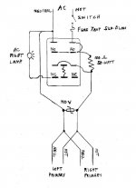
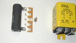
You are correct. The 8 seconds is too slow. A 20 ohm resistor might be more suitable. I went with the power resistor I had handy, plus I did not know at the time how many amps might be soft started at one time. Building a soft start circuit is simple to do if one wants to do it. I went for a more plug n' play approach. Here is my wiring diagram and a picture of the power resistor, a stand off connector, and the time delay relay.
The trick is to find an AC powered relay suitably sized for the occasion. I got mine off (where else) eBay.
Attachments
Last edited:
A more realistic and circuit stable approach I've composed: Parallel a pair of 6800uf and a bypass (2.2uf?) cap to replace each original 10000uf filter cap. This would allow for a little more capacitance, but hopefully not enough to cause issues; plus lower resistance thanks for the split overall value. All the caps would be soldered tabs, but I'd strap all the caps together before making to electrical connection, so it would have a clean look with solid connections.
Am I missing something with this design? Did I forget something? This would still be in coordination with upgraded 35A bridge rectifier.
Am I missing something with this design? Did I forget something? This would still be in coordination with upgraded 35A bridge rectifier.
A more realistic and circuit stable approach I've composed: Parallel a pair of 6800uf and a bypass (2.2uf?) cap to replace each original 10000uf filter cap. This would allow for a little more capacitance, but hopefully not enough to cause issues; plus lower resistance thanks for the split overall value. All the caps would be soldered tabs, but I'd strap all the caps together before making to electrical connection, so it would have a clean look with solid connections.
Am I missing something with this design? Did I forget something? This would still be in coordination with upgraded 35A bridge rectifier.
That would be a fine upgrade.
Not really necessary, but you may also want to fit a ~6.8K 2W resistor in parallel with each cap bank to discharge the caps at power off. With this fitted I find they discharge more evenly reducing turn off thumps, and it's convenient when working on the amp (setting bias, etc).
I have been working on this AC soft-start ckt as well. I am basing it on the old Pioneer SX-1250 design, since I have acquired a used SX-1250 transformer. You can down-load the SM from.
Main scan page
I have attached my schematic and BOM. Note I have not fabricated this ckt yet, but it is rather simple.
Regards
Rick
Main scan page
I have attached my schematic and BOM. Note I have not fabricated this ckt yet, but it is rather simple.
Regards
Rick
Attachments
Soft-start ckt's
Oop's previous schematic has been updated, see attached. I welcome feedback as well.
I have the other sections designed and laid out too, but off topic for this discussion.
I based this stuff from the SX-1250 & other Pioneer amplifier designs as well as the National power supply app note as used for thr LME498xx series of parts
1) main rectifier & filter
2) regulators & protection ckt
3) LME49830 + Lateral MOSFET
Thx Rick
Attachments
Last edited:
C1, according to National ap1849, to protect against turn-on/off spikes, Pioneer did not use it = optional
C3, Nationals idea, another optional, yes a film cap would do as well= better. I used 5mm lead spacing.
Thinking of adding 2 triacs, controlled by opto's, in series with the line & in parallel with K1 so that I can add MCU control option, would require separate power for MCU, more PS what can I say.

Real easy to install a 2.5Ω thermistor on the terminal strip behind the power switch, I've done it several times.
http://www.digikey.com/product-detail/en/UVP1C471MPD/493-6081-ND/2539563
http://www.digikey.com/product-detail/en/ECE-A1AN471U/P1158-ND/227599
http://www.digikey.com/product-detail/en/ECE-A1CN471U/P1170-ND/227611
http://www.digikey.com/product-detail/en/ECE-A0JN471X/P1146-ND/227587
http://www.digikey.com/product-detail/en/UVP1C471MPD/493-6081-ND/2539563
http://www.digikey.com/product-detail/en/ECE-A1AN471U/P1158-ND/227599
http://www.digikey.com/product-detail/en/ECE-A1CN471U/P1170-ND/227611
http://www.digikey.com/product-detail/en/ECE-A0JN471X/P1146-ND/227587
Last edited:
While in theory it could be done, I would not recommend trying it at all.
The bias circuit would have to be redesigned for the much higher gate voltages, and temperature compensation. The pin-outs are different. Source resistors would need to be added. The device threshold voltages would need to be matched. The frequency compensation would need to be changed. Fold-back current limiting would be a good idea, the IRF type do not protect themselves like the Hitachi type do. Etc.
But yes, it is possible.
Hitachi=Renesasthe IRF type do not protect themselves like the Hitachi type do. Etc.
- Home
- Amplifiers
- Solid State
- Hafler DH-200/220 Mods