anatech said:
There is a cult status these parts have achieved also that you are only feeding. I can not allow you to misled people in this way. As you know, this is absolutely not personal. It has only to do with many, many years of observed failures.
Chris,
Cult status?
Yep, we live in different worlds, all right. Not once have I ever talked to another DIYer who advanced the idea of a multi-turn pot--I came to use them on my own. There certainly hasn't been the huge groundswell of support for multi-turn pots here that you seem to imply, as it would have erupted in numerous threads over time. And presumably would have evoked the same "Repel the heathen invaders! Kill them all--let God sort them out!" response from you.
'As you know, this is absolutely not personal.'
Actually, I was thinking about your behavior as I drove home last night and the only apt comparison I could think of was the tirades that Fred D. used to unleash on anyone who dared disagree with him.
I will now bow out and let you continue your anti-multi-turn rant by yourself. But please restrict yourself to things that I have actually said; not things that you have imagined.
Grey
I think that we have learned enough about pots for the moment and I agree- lets move on.
Realistically, I think that the high voltage transformer of the US version Hafler is what discouraged me about the PLH . The Hafler that Nelson had seen was an international version that he thought could be wired for 220 to run on 120 and put out half the voltage. When we discovered that the US version didn't have the 220v leads I kind of dispaired- even though Nelson felt that it could be made to work..
I really hated to replace the transformer, because then you are pretty much just using the case.
Also, as was mentioned, it is tough to rip apart an amp that works fine and puts out a decent amount of power...
Incidentally, I have another orphan amp - a BK ST 202 Does it have any virtue or is it another candidate for upgrading?
Hello everyone,
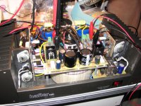
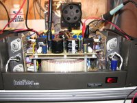
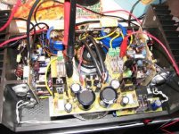
Merry Christmas. Finally had sometime to finish modifying my Musical Concepts modified DH-220GXB. Hard to get spare time with 1 and 3 year old boys.
I added a separate transformer and a regulator for the driver boards and placed it above the MC toroid transformer. To the right, just above the power switch I also installed a soft start circuit. This is the amp that got me started on the DIY path. IMO the GXB mod was the best of the original DH-220 mods from Musical concepts. I started with the original M mod, then DX, FX, GX and finally end with the GXB.
Attachments
Sze said:Hello everyone,
..
I added a separate transformer and a regulator for the driver boards and placed it above the MC toroid transformer. To the right, just above the power switch I also installed a soft start circuit. ...
Hi
Very nice integration and available space optmization !!

What is the voltage you used fro the driver stage?
I see you used IC regulators but which one?
Thanks
Fab
Dick West said:Congrats on your impressive work!!
Can you characterize for us the before and after differences in the sound of the amp with the regulators? Does regulating the voltage to the PCBs make much difference?
Hopefully I can notice a difference for all the work that went into this little project. The amp has not been used in my system for over 6 months during this latest work in progress.
I'll report on sound at a later date. I'm letting the amp burn in for a lititle while.
Sze
fab said:
Hi
Very nice integration and available space optmization !!
What is the voltage you used fro the driver stage?
I see you used IC regulators but which one?
Thanks
Fab
The front end circuit is set at 60v regulated and the driver transistor and output stage is at 65v unregulated. A 55v+55v transformer provides 80v+80v to the regulators.
Actually Fab, there are no ic used in this regulator. It is all descrete components. There are 2 sets of pass transistors. The prereg uses TIP 122/127 and the main regulator uses K216/J79 mosfets.
regards,
sze
Sze said:
The front end circuit is set at 60v regulated and the driver transistor and output stage is at 65v unregulated. A 55v+55v transformer provides 80v+80v to the regulators.
Actually Fab, there are no ic used in this regulator. It is all descrete components. There are 2 sets of pass transistors. The prereg uses TIP 122/127 and the main regulator uses K216/J79 mosfets.
regards,
sze
do you mind sending me a mail ........ I can't reach you via board mail thingie .........
voltage regulator for DH-200
Hello guys!
Very, very nice thread!!!
I'm an Hafler fan from more than 10 years, I don't modify old Haflers, I built them from scratch instead!
Someone could think it is a waste of money but from my experience you end up having a great piece of gear, far better than the original amp and capable of being always near the best (and way more expensive) other amplifiers I've compared to, not to mention the great number of the amps in his price range it killed out.
I include the 2SJ162/2SK1058 direcly on the board, I find it useful since I don't mind using existing mosfets and heatsinks.
The modifications I did are all the "simple" ones that you already discuss here (correct grounding, increased filter capacitors, soft start, mf resistors, etc), except from the regulated power supply. I have a question about this: seems that some of you are worried about the effect of a lower voltage on the "small signal" part of the amp due to the voltage drop on the regulator, but doesn't the R28-R34 already cause a voltage drop in the original configuration too?
Ciao!
Paolo
hello again... i dont think 47 ohms causes much in the way of a voltage drop. easy enough to ck with a dvm, regulating the driver section would cause the front end to clip befor the outputs. several schools of thought to boost voltage for the driver section range from additional transformers to simple diode voltage doubler regulated from there 10+ volts or so above the rail to drive the final outouts to their full potential.
Good luck, let me know how it goes as i have an older dh200 that i am in the process of modernizing some pc 19 driver boards ...
Elwood
Good luck, let me know how it goes as i have an older dh200 that i am in the process of modernizing some pc 19 driver boards ...
Elwood
Regulating driver section
hello eyoung
If you require higher driver voltage you can do the same method as Sze in previous post but use a higher transfo voltage. But, in my opinion, this will only give you original maximum power (about 130Wrms into 8 ohms I measured for the DH-200 and DH-220 may be a little higher). Of course using lower voltage for the driver will reduce this max output power. For the clipping concern, for mosfet output stage it is not a problem -as already mentioned by Mr Nelson Pass in another thread a few yeaes ago from what I remember. I also tested lower driver voltage and clipping does not show any major problem.
eyoung said:hello again... i dont think 47 ohms causes much in the way of a voltage drop. easy enough to ck with a dvm, regulating the driver section would cause the front end to clip befor the outputs. several schools of thought to boost voltage for the driver section range from additional transformers to simple diode voltage doubler regulated from there 10+ volts or so above the rail to drive the final outouts to their full potential.
Good luck, let me know how it goes as i have an older dh200 that i am in the process of modernizing some pc 19 driver boards ...
Elwood
hello eyoung
If you require higher driver voltage you can do the same method as Sze in previous post but use a higher transfo voltage. But, in my opinion, this will only give you original maximum power (about 130Wrms into 8 ohms I measured for the DH-200 and DH-220 may be a little higher). Of course using lower voltage for the driver will reduce this max output power. For the clipping concern, for mosfet output stage it is not a problem -as already mentioned by Mr Nelson Pass in another thread a few yeaes ago from what I remember. I also tested lower driver voltage and clipping does not show any major problem.
voltage drop
Hi Elwood,
I will check the voltage droop with a DVM, but rougly 47 ohm means 5V per 100mA, and you have also the voltage droop on D12/D11... It is possible to use a low droop voltage regulator instead of the 78XX/79XX versions.
I made a test some years ago, supplying the DH-200 with a variac in order to be able to hear the effects of a voltage variation on the sound. Well, of course I wasn't using all the power of the amp (the room was quite small, the loudspeaker about 89dB, and the listening level for this test was not high), but the difference in the sound was evident.
Was it due to a different bias? Or a different voltage on the VAS? I don't know, but the result has been clear.
If needed, since I use toroidal transformers, I can wind another couple of windings to have the right voltage. Now the only problem is to define "right voltage".... Shall I reference to the voltage measured on C7/C10 at the nominal mains voltage?
I'm in the process now of making some boards, so I wish to include all the important modifications: other suggestions other than this voltage regulator?
Ciao!
Paolo
eyoung said:hello again... i dont think 47 ohms causes much in the way of a voltage drop. easy enough to ck with a dvm, regulating the driver section would cause the front end to clip befor the outputs. several schools of thought to boost voltage for the driver section range from additional transformers to simple diode voltage doubler regulated from there 10+ volts or so above the rail to drive the final outouts to their full potential.
Good luck, let me know how it goes as i have an older dh200 that i am in the process of modernizing some pc 19 driver boards ...
Elwood
Hi Elwood,
I will check the voltage droop with a DVM, but rougly 47 ohm means 5V per 100mA, and you have also the voltage droop on D12/D11... It is possible to use a low droop voltage regulator instead of the 78XX/79XX versions.
I made a test some years ago, supplying the DH-200 with a variac in order to be able to hear the effects of a voltage variation on the sound. Well, of course I wasn't using all the power of the amp (the room was quite small, the loudspeaker about 89dB, and the listening level for this test was not high), but the difference in the sound was evident.
Was it due to a different bias? Or a different voltage on the VAS? I don't know, but the result has been clear.
If needed, since I use toroidal transformers, I can wind another couple of windings to have the right voltage. Now the only problem is to define "right voltage".... Shall I reference to the voltage measured on C7/C10 at the nominal mains voltage?
I'm in the process now of making some boards, so I wish to include all the important modifications: other suggestions other than this voltage regulator?
Ciao!
Paolo
If you are cloning the DH-200 circuit I hope you are including a circuit to null out DC offset, like the one on the DH-220 boards.
Also, the resistor/diode combo on each power supply rail to these boards is meant to provide some decoupling between the VAS and the output drivers, to help protect the voltage gain circuits from power supply modulation created by heavy transients in the output MOSFETs.
Also, the resistor/diode combo on each power supply rail to these boards is meant to provide some decoupling between the VAS and the output drivers, to help protect the voltage gain circuits from power supply modulation created by heavy transients in the output MOSFETs.
Re: voltage drop
Have you tried to change ONLY the driver voltage or the voltage of both the driver and output stage?
Anyway, regardsless of the driver voltage used, lots of today's "hi-fi" power amps have a regulated voltage driver stage so the increase in parts must justify it otherwise peoples are crazy...
Good luck and keep us posted on your progress")
pidigi said:
...I made a test some years ago, supplying the DH-200 with a variac in order to be able to hear the effects of a voltage variation on the sound. Well, of course I wasn't using all the power of the amp (the room was quite small, the loudspeaker about 89dB, and the listening level for this test was not high), but the difference in the sound was evident.
Was it due to a different bias? Or a different voltage on the VAS? I don't know, but the result has been clear...
Have you tried to change ONLY the driver voltage or the voltage of both the driver and output stage?
Anyway, regardsless of the driver voltage used, lots of today's "hi-fi" power amps have a regulated voltage driver stage so the increase in parts must justify it otherwise peoples are crazy...
pidigi said:
...I'm in the process now of making some boards, so I wish to include all the important modifications: other suggestions other than this voltage regulator?
-Double mono power supply (if transfo have 2 separate windings) for the output stage;
-Cascode the VAS with low Cob transistors
Why do not incorporate most or all improvements suggested im this thread?
Good luck and keep us posted on your progress
pidigi said:No, I didn't include the DC correction circuit. I always use matched bjt in the input stage and I believe that this is useful also for lowering the distortion.
Ciao
Paolo
- Home
- Amplifiers
- Solid State
- Hafler DH-200/220 Mods