Attempt to post, this image (related to prior post) did not upload.
Front right. What you got going on there? Looks pretty much upgraded. Nice and clean too.
i'd check all the power mosfets first.
if the mosfets are all good, i'd fix the amps or worst case, build different driver boards for them.
otherwise, i'd junk the amps.
mlloyd1
if the mosfets are all good, i'd fix the amps or worst case, build different driver boards for them.
otherwise, i'd junk the amps.
mlloyd1
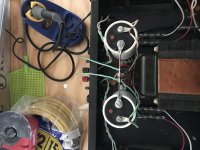
Picked these two up for $100. Neither worked. One had cut cord so it may be a loss. Looks like they’ve both been tinkered with a few times over. I started to rewire one and investigate some obvious stuff and here I am...
Gut ‘em and rebuild? Find fix and flip? Back to stereo (both mono) I you had these what would you do with them?
Can I just run the grounds from pin 6 straight to the center bar instead of the to the output and then the center. This is configured for mono.
I would maintain the grounds runs exactly as original. Changing things like that can run into trouble. However, do make sure that the three wires connected to the ground strap between the filter caps are all soldered together as close as possible to the center of the strap. Your amps show them spaced out. Back when I was a tech at Hafler, fixing that ground point was one of the first things we'd do to most kit-built amps.
Also, I would suggest changing out the input 'lytic to a film type like polypropylene. BTW, another former ex-Halfer tech/engineer is selling upgrade kits for the DH200 for very reasonable prices on eBay under the name Qua-Co Audio.
The "centre bar" between the two smoothing capacitor is part of the charging circuit.Can I just run the grounds from pin 6 straight to the center bar instead of the to the output and then the center. This is configured for mono.
Short period high current pulses pass along this link.
Do not use this link as a reference for any part of the audio.
Instead take a single wire (twisted with the other two power wires) from this link to your audio circuit.
Hi,
in my mind it's always worth to make them work again. Basic informations can be foung at Hafler - Perfecting high fidelity audio for over 60 years.. Also for the output-Mosefets, if they are really defect, Exicon devise in TO-3 cases can be used and they are still available. Another possibilty is the use of PC-19 boards from the DH-220, which are atill available as bare pcbs from Quaco.
other offers for upgrading the dh-200 on ebay asked a astronomic high price imho.
BR
Günni
Hafler DH220 Inrush thermistor - size/rating?
I am dusting off a DH220 that I built back in 1988. It works, but from what I've read in this forum it would be a good idea to put in a thermistor to protect the power switch. From reading here, its clear that many here have done this, but I can't seem to find the specs on what thermistor to buy? I saw 5 ohm, but others said 2? Does it matter? Amp rating?
Also, does it go between switch and fuse, or before the fuse? Where?
None of the caps look like they've gone bad. Short of replacing boards (which I know some have had great luck with...), are there any other minor mods/upgrades that I should consider doing? I haven't used it in a long time, so I don't know if the extent to which the sound has degraded, or alternatively, could be greatly improved with minor tweaking.
Thanks!
I am getting ready to replace some failing caps and do some minor mods to a DH200 I built in the early 80s. In many places threads on this an other sites reference the signal path and logical sections of the amplifier circuit when discussing mods. But for many of us, determining the signal path is no sure thing, let alone mapping out what each section of the amp is doing.
So, if anybody has or is willing to take a copy of the schematic, highlight the signal path and label the logical components, please post a picture.
Thanks!
So, if anybody has or is willing to take a copy of the schematic, highlight the signal path and label the logical components, please post a picture.
Thanks!
Maybe to read this would help to clarify the amp a bit more;
http://hafler.com/pdf/archive/DH-200_amp_man.pdf
So has there been any progress towards making the Cordell designed boards a reality?
http://hafler.com/pdf/archive/DH-200_amp_man.pdf
So has there been any progress towards making the Cordell designed boards a reality?
Hello, what is de value of the fuse connected to the mains? The single one next to the power switch and transformer?
And the size?
I haven’t seen those fuses in Spain... at least in local shop.
I’m about to grab one of these amps plus preamp.
Thanks
Hi,
for 110/120V operation 5A (slo blo) for 220/240V operation 2,5A (Slo-Blo). As stated in the manual 5A(slo-blo) 3AG, or metric measurements 6,3mmx32mm, also available at Amazon, Mouser (https://www.mouser.de/datasheet/2/240/Littelfuse_Fuse_313_315_Datasheet.pdf-476752.pdf), Reichelt .
Good luck
Maybe to read this would help to clarify the amp a bit more;
http://hafler.com/pdf/archive/DH-200_amp_man.pdf
So has there been any progress towards making the Cordell designed boards a reality?
Hi phase,
just working on a pc-25 follower for the Hafler DH-120 or P-125, according to the design of Bob Cordell, also on a 2 pair Mosfet circuit with TO3p (TO-247) lateral Mosfets (Exicon or Renesas) based on Bobs design.
BR
Günni
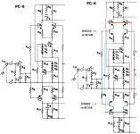
A cascode rewire
I used to fix and mod the DH200 back in the late 70's. Back then, a number of them were starting to generate significant DC offsets due to C-B leakage in the input stage. I fixed one by wiring in some other complementary small signal transistors I had (Motorola 2N5210, 2N5087 of Tiger amp fame) as new inputs, with the original transistors as cascode tops, like this:

This was done by just pulling the emitter and base leads of the original devices from the board and inserting the new added devices into the holes and twisting and wiring the arrangement with a few jumpers.
This put the C-B voltage of the (new) input transistors at around 100mV or so, so they didn't leak, even if the original high voltage input transistors leaked moderately. The DC offset dropped to nearly zero. When I started modding the amps later, I added an integrator and inverter circuit using TL074 opamps to form DC servos, making the cascode leakage fix probably un-necessary, but I assumed then (with no way to measure or simulate) that distortion would be better with the cascode. I don't have any Hafler amps anymore -- the last one I had developed a mechanical hum/buzz in its power transformer that was driving me nuts so I gave away the amp, so no way to measure anything now.
Maybe some here can comment whether my quickie-cascode arrangement was an improvement or degradation of the original input arrangement?
I used to fix and mod the DH200 back in the late 70's. Back then, a number of them were starting to generate significant DC offsets due to C-B leakage in the input stage. I fixed one by wiring in some other complementary small signal transistors I had (Motorola 2N5210, 2N5087 of Tiger amp fame) as new inputs, with the original transistors as cascode tops, like this:
This was done by just pulling the emitter and base leads of the original devices from the board and inserting the new added devices into the holes and twisting and wiring the arrangement with a few jumpers.
This put the C-B voltage of the (new) input transistors at around 100mV or so, so they didn't leak, even if the original high voltage input transistors leaked moderately. The DC offset dropped to nearly zero. When I started modding the amps later, I added an integrator and inverter circuit using TL074 opamps to form DC servos, making the cascode leakage fix probably un-necessary, but I assumed then (with no way to measure or simulate) that distortion would be better with the cascode. I don't have any Hafler amps anymore -- the last one I had developed a mechanical hum/buzz in its power transformer that was driving me nuts so I gave away the amp, so no way to measure anything now.
Maybe some here can comment whether my quickie-cascode arrangement was an improvement or degradation of the original input arrangement?
Attachments
Hi bwaslo,
I also repaired tons of these back then. All you really had to do was to match the beta for the input pairs, replace the capacitors and match the transistors further up the road there. DC offset was caused by a number of things, but beta mis-match was one big one. Capacitors were another. If you did that, you would typically end up with less than 10 mV DC offset, less than 5 mV for a good matching job.
-Chris
Why not build a couple kits, tehn as your soldering skills improve, along with your knowledge, you will get far more out of a more advanced project. It might not look or sound like much, but working on an amplifier really does require a good understanding as to how it works, and what subsections do. It isn't about blindly following what you think are good instructions off the internet. Once you understand the basics, you can better determine what is and isn't a good idea.
Many improvements require matched parts, and also the possibility that the amplifier can either go into oscillation or have worse performance than it did stock. So you absolutely do need an oscilloscope (a used good one would be my suggestion). To set bias current and DC offset you will be measuring in the mV region, so you need accurate reading , so a minimum of 1.1 mV is required from a good meter. Therefore you should be looking at a Fluke or Keysight meter. I have some old HP meters (974A) that has a basic accuracy of 0.05% that I love using. My new Keysight meter is still 0.05% basic DC accuracy. A bench meter will probably give you better service with better accuracy. OTher brands can claim accurate readings, but they either fail their specs out of the box, or they drift quickly over time. The Fluke and HP / Agilent / Keysight (the same company) do hold their calibration extremely well.
So you will also need some kind of distortion analyser - used is fine. If you can find an Amber, HP or Tektronix analyser you're off to a good start. THe HP 8903 (probably expensive), 339A, 331A ~ 334A will all provide you with great service. With the HP 331A ~ 334A, you will also need an oscillator. A single frequency 1 KHz, low distortion oscillator will serve to give you good readings. Function generators are not useful here (outputs are sine, triangle and square wave typically) due to their very high distortion.
These items are used for most things on the bench, so no money wasted. The distortion analysers are normally only used for audio device testing such as amplifiers, tuners, CD players, tape decks and so forth. Your 'scope and meter are about as important as your hand tools. One last point, you need a soldering station with controlled temperature. Don't attempt to use "hobby iron" without temperature control. This will destroy PCBs and components as well as being hard to use. It's enough to make you quit the hobby. Good basic tools will allow you to enjoy what you are doing while also letting you do a good job.
-Chris
- Home
- Amplifiers
- Solid State
- Hafler DH-200/220 Mods