Hello everyone,
I am new to this forum. I have read this thread a few times now and have absorbed alot of good info.
I have a factory built DH-220 that i recently picked up a few months ago. I have already gone through and set the bias and DC offset as close back to specs. The amp sounds great. I am getting ready to replace all the electrolytic capacitors to freshen it up. Here is what i am planning.
2 x 18,000mfd 75v United Chemi-con
2 x 220mfd 10v Nichicon Muse ES bi-polar
4 x 100mfd 100v Nichicon Muse KZ
1 x Fairchild GBPC3508 bridge rectifier 35amps
Now i have read alot about using a bypass cap on the main power supply capacitors. I am just not clear on what value to use, there are alot of different values being used in this thread. I also not sure if i even need to add them? Also there has been alot of debate over using Nichicon or the Elna Silmic II caps. I have no problem switching the Nichicons to them. I am powering some Polk Rt55's that have crossover caps upgraded.
I plan on ordering from Digi-key in the next day or so. Any comments or info would be great.
Thank you
Thanks for the info,
One other question....
The main power supply caps i was planning on using were the United Chemi-con 18,000mfd 75v. Reading the spec sheet it says they are "high" ripple current. From reading is it not better to have "low" ripple current on power supply capactors?
The specs are
Ripple Current = 9.4amps
ESR = 22 mOhm
Will these work?
Thank you
I am likely to get a DH200, from a friend. Quite frankly, I am going to replace the power transformer with a toroid from Antek, which has an electrostatic shield and an external shield (option), but I am willing to lower voltages by 10 volts or so to reduce strain on the components - esp. output transistors (I also plan to re-cap the electrolytics in PS and bypass on the PCBs).
So, if I choose a lower transformer so I end up - after the bridge, with +/- 40-50 volts, is the anything else I have to do in terms of replacing components? Also how would re-biasing be affected?
So, if I choose a lower transformer so I end up - after the bridge, with +/- 40-50 volts, is the anything else I have to do in terms of replacing components? Also how would re-biasing be affected?
I am likely to get a DH200, from a friend. Quite frankly, I am going to replace the power transformer with a toroid from Antek, which has an electrostatic shield and an external shield (option), but I am willing to lower voltages by 10 volts or so to reduce strain on the components - esp. output transistors (I also plan to re-cap the electrolytics in PS and bypass on the PCBs).
So, if I choose a lower transformer so I end up - after the bridge, with +/- 40-50 volts, is the anything else I have to do in terms of replacing components? Also how would re-biasing be affected?
For the only reason of the voltage reduction, you can keep the rest of the parts. However, you can at least upgrade the electrolytic caps for low ESR on the board and especially the feedback cap and double the value if space allows....for audio reasons...
For the bias it should not change b/c of the lower voltage used but you can experiment to increase it since you heatsink will heat less with less voltage on the output transistors.
Keep in mid that with 40 vdc, you reduce a lot the total possible audio power of the amp but it still may be sufficient for your needs.
Good luck
Fab
Keep in mid that with 40 vdc, you reduce a lot the total possible audio power of the amp but it still may be sufficient for your needs.
Fab
I understand, but my current but amp puts out about 14 watts and it is generally OK, I just want a bit more power so about 40 watts would be great. My crest factor is about 15% because I listen mostly to jazz, renaissance music, country folk and some rock (but not headbanger music). After looking at Antek transformers and estimating the space (from the manual), I think that a toroid of about 36 + 36 volts at 600 VA will be sufficient for me.
Have you considered using your current transformer in an external case and then drop about 10v in a simple voltage regulator.
Or use a small bucking transformer on the primary.
I understand, but my current but amp puts out about 14 watts and it is generally OK, I just want a bit more power so about 40 watts would be great. My crest factor is about 15% because I listen mostly to jazz, renaissance music, country folk and some rock (but not headbanger music). After looking at Antek transformers and estimating the space (from the manual), I think that a toroid of about 36 + 36 volts at 600 VA will be sufficient for me.
With 36 + 36vac you get about +/-50vdc after rectification so about 125wrms/8 ohms. Unless you mean +/- 36vdc....thus 25vac-0-25vac transfo. With +/-36vdc you get about 55wrms or so into 8ohms. Note that this is resistive power and not reactive.
If you need only 25-30 watts you can get almost full class A as suggested by Nelson Pass. But to do so, you should select a lower transfo voltage such as 18vac-0-18vac (or 20vac). As a compromise you can select something in-between...
Fab
Last edited:
I misunderstood the Hafler transformer specs
I meant toroid with two secondaries, so I would get +36VAC/0/-36VAC, but I thought the Hafler had a transformer that put out more Volts AC . I am actually trying to reduce the VDC voltage on the rails, so I misunderstood the Hafler manual and the on-line discussion. A 24VAC/0/24VAC toroid is what I will get.
To others, I do not have space for a bucking transformer, and a voltage regulator for the output would add more complexity (and be hard to physically fit in the case). I am already planning to put the DIYAudio inrush protector, and I am considering the speaker protector because if one of the rail fuses goes and the other one does not, I will have VDC on the output which will blow my expensive speakers. I do not trust the rail fuses at all.
With 36 + 36vac you get about +/-50vdc after rectification so about 125wrms/8 ohms. Unless you mean +/- 36vdc....thus 25vac-0-25vac transfo. With +/-36vdc you get about 55wrms or so into 8ohms. Note that this is resistive power and not reactive.
If you need only 25-30 watts you can get almost full class A as suggested by Nelson Pass. But to do so, you should select a lower transfo voltage such as 18vac-0-18vac (or 20vac). As a compromise you can select something in-between...
Fab
I meant toroid with two secondaries, so I would get +36VAC/0/-36VAC, but I thought the Hafler had a transformer that put out more Volts AC . I am actually trying to reduce the VDC voltage on the rails, so I misunderstood the Hafler manual and the on-line discussion. A 24VAC/0/24VAC toroid is what I will get.
To others, I do not have space for a bucking transformer, and a voltage regulator for the output would add more complexity (and be hard to physically fit in the case). I am already planning to put the DIYAudio inrush protector, and I am considering the speaker protector because if one of the rail fuses goes and the other one does not, I will have VDC on the output which will blow my expensive speakers. I do not trust the rail fuses at all.
Mono Hafler Update
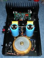
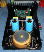
I took apart my mono Haflers last winter, and removed the DH220 boards/outputs/heat sinks I had in them.
I had already made numerous power supply and wiring mods in the amps, which are visible in the photos.
The 220 boards were oem in design, but had upgraded electrolytics, film caps & resistors.
I replaced them with DH200 heat sinks & outputs, along with an upgrade driver board kit that I picked up from eBay seller qua-co.
Hafler DH200 High END Audiophile Upgrade KIT Toshiba Jfet Cascode Topology | eBay
They are nicely layed out, easy to assemble with detailed instructions and the boards are shorter than the original Hafler boards, which makes for easier wiring.
If you check the description, he lists the improvements that he made over the original Hafler design.
Using the kit is a lot easier/quicker than sourcing the various parts, overhauling the original boards with premium components, and hoping that the more difficult to source/match input transistors are all in good shape.
The end result is a an amp with plenty of punch, not the slightest bit edgy or harsh at any frequency, is easy to listen to over extended periods (not fatiguing), great soundstage, separation, depth etc.
Although I do enjoy overhauling the original boards myself, I would not hesitate to use the kit again.
Attachments
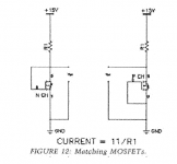
How close do the output devices need to be matched ? Like when using this test jig would a VGS mis match of 1.35v and 1.5v still be ok ?
I don't have any knowledge regarding that myself, but am curious to know as well.
Have you tried comparing known working matched sets already?
It should give you a good indicator on the tolerance range.
I picked up one of these awhile back, mostly for comparing input devices:
Transistor Semiconductor Parameter Tester Meter DY294 | eBay
Figured I could order batches from places like Mouser and match devices myself.
Just haven't got around to it yet though.
How close do the output devices need to be matched ? Like when using this test jig would a VGS mis match of 1.35v and 1.5v still be ok ?
As you may know, this figure came from Nelson Pass's article on matching MOSFETS. There is some guidance on VGS matching tolerance within it. His guidance is for 0.2 volts or less for output MOSFETS (with 0.1 volt being a reasonable target).
But these are lateral mosfets with the negative temp. coefficient so I wonder if they have to be matched that tight ?
Maybe they don't have to be matched so tightly. As I understand it, the concern is not so much thermal runaway, but even-sharing of the current among the devices, and that applies to lateral MOSFETS too.
I did not see post #1234 before I posted mine, and it has good advice. I have some Hafler-graded MOSFETS here (with a 3, 4 ,5 etc. stamped on them) that I can check VGS on, if that would be helpful.
I did some VGS measurements on some spare MOSFETS (Hitachi 2SJ49 and 2SK134), graded by Hafler, and VGS matching was about 1/100 of a volt within a grade, (with a maximum of 4/100) and this was for supply voltages from 5 to 25, in 5-volt increments, with a 50-ohm series resistor for all measurements. Some of the VGS differences may be due to slight differences in what should be constant supply voltages, which were on the order of 1/50 to 1/10 volt.
Dick West may have some ideas on this too; he has a Hafler MOSFET tester.
Unfortunately Dick West is no longer with us.
According to the information in post 1110, the link included indicates that he passed away on Feb 20, 2013
I enjoyed reading his posts on his modding DH200 and DH220s.
- Home
- Amplifiers
- Solid State
- Hafler DH-200/220 Mods