Woody,
One of the most common problems with the vintage DH-200 amps is that the first 4 transistors (in the input differential amplifier section) have drifted out of spec. These transistors must be matched on hFe or you will get DC offset. You can't just replace parts, the transistors must be matched. Do you have a meter that can measure hFE? If so you might get 20 or so of each of the NPN and PNP transistors, measure them, and get some matched pairs.
The DH-220 has a small circuit that includes a variable resistor to null DC offset. The DH-200 does not.
Yeah, getting matched pairs is a daunting task. Here is a simpler solution that may work for you as it has for me a couple of times in the past:
In The Audio Amateur 1/83 p. 55-56 Erno Borbely suggested to hang a 100K pot between the card's power supply rails and take the output of its wiper, via a 1 meg resistor, to the circuit end of R3.
I did this with a 1/2 watt multi turn cermet 100K variable resistor and used a metal film 1 meg resistor to R3. So, it would seem that injecting a small amount of either the + or - voltage to the amp's input at R3 is the solution. Furthermore, a small film cap across the ±60VDC attachments to the variable resistor will help reduce noise.
If you study the DH-220 schematic you can see the similarity to the above suggestion.
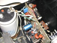
Here is how I attached these extra components to a DH-200 PCB.
You can see the small blue variable resistor attached to the upper left hand corner of the PCB. I drilled tiny holes for its mounting pins and on the back side of the PCB ran a wire from one rail to one pin and jumpered the other pin the rail on that side. From the wiper I soldered the 1 meg resistor and attached it to the circuit end of R3.
Insulating shrink tubing was used as needed.
This circuit has tamed as much as 300 mV DC offset. When the circuit is turned on the DC offset does swing a lot until the circuit warms up and stabilizes. The amount of swing is probably because of the lack of matching of components but the 3 piece circuit above can bring the DC offset voltage down to almost zero as the variable resistor is adjusted.
In The Audio Amateur 1/83 p. 55-56 Erno Borbely suggested to hang a 100K pot between the card's power supply rails and take the output of its wiper, via a 1 meg resistor, to the circuit end of R3.
I did this with a 1/2 watt multi turn cermet 100K variable resistor and used a metal film 1 meg resistor to R3. So, it would seem that injecting a small amount of either the + or - voltage to the amp's input at R3 is the solution. Furthermore, a small film cap across the ±60VDC attachments to the variable resistor will help reduce noise.
If you study the DH-220 schematic you can see the similarity to the above suggestion.
Here is how I attached these extra components to a DH-200 PCB.
You can see the small blue variable resistor attached to the upper left hand corner of the PCB. I drilled tiny holes for its mounting pins and on the back side of the PCB ran a wire from one rail to one pin and jumpered the other pin the rail on that side. From the wiper I soldered the 1 meg resistor and attached it to the circuit end of R3.
Insulating shrink tubing was used as needed.
This circuit has tamed as much as 300 mV DC offset. When the circuit is turned on the DC offset does swing a lot until the circuit warms up and stabilizes. The amount of swing is probably because of the lack of matching of components but the 3 piece circuit above can bring the DC offset voltage down to almost zero as the variable resistor is adjusted.
Attachments
matched pairs
Hi!
I've used the 2N5551 and 2N5401 matched sets from www.tech-diy.com and they work perfectly for me.
Hope this helps,
Paolo
Hi!
I've used the 2N5551 and 2N5401 matched sets from www.tech-diy.com and they work perfectly for me.
Hope this helps,
Paolo
hello fellow hafler addicts,
If you go back to the begining of this thread you will find some discussion about star grounding and how the dh200 and dh220 need some grounding issues fixed. check out this link ....http://www.musicaldesign.com/mc_amp_mods.htm. download their manual for the PA-3. read and absorb and then read what FAB and Slowhand have to say early on in the thread about mods to dh200/220.
Regards, Elwood
2n5551 and 2n5401 were used in the dh220 these are some of my favorites, I have used them in several other amps as well , they work great in the pass a-40.
I have had similar results in fixing the grounding problems in the hafler amps and others as well.
following good grounding practices (or not) can mean the difference between a stellar performer and a speaker smoker.
In the case of hafler amps it makes for a measuerable and audible improvment.
I have had similar results in fixing the grounding problems in the hafler amps and others as well.
following good grounding practices (or not) can mean the difference between a stellar performer and a speaker smoker.
In the case of hafler amps it makes for a measuerable and audible improvment.
DH-500 , XL-600 +- 90- 100 volt Regualted power supplies
I am currently rebuilding one Hafler DH-500 amp and one XL-600 using dual toroidal transformers, IXYS rectifiers and Musical Concepts PA-3E boards with black gate caps, and 4 - 39,000 uf main caps per amp.They will be used to bi-amp my Polk SDA-SRS speakers which I just purchased on E-bay and have since reworked with new Mills resistors and Polyproplyene caps.
Most Of my Listening will be two channel with the SDA-SRS's only
I am looking for a state of the art simple power supply -+ 95 volt for the front end, low level and drivers. I plan to leave the Mosfets unregulated, using the main caps and toroidals. I would like to have the regulator self contained in the amp
What is the power supply design that will give me the best
results, for my new system. Also I need advice regarding removing
the resistor that separates the Mosfet drivers from the front end. And whether I should have a regulator for each board. The Musical Concepts board provides for the ability to power the front
end from a separate source, which is inherent in the XL-600, but they do not recommend it.
John Hillig from Musical Conceptss ays that regulating the front end with his design won't yield much in better sound.
I have had excellent results in the past using regulation for everything, I have built.
I have built several power supplies, based on Boak, Sultzer and Jung designs , using NE-5534 and LM317-LM337's and floating zener designs, for other Hafler, Dynaco 416, Leach Super Amps, and the Marsh pre-amp about 20-30 years ago. But haven't done much since then. In the past I built a Marshall Leach super amp and regulated each stage using a modified floating Sultzer design, including the output stage, and ran it Class A with 2 amp bias current wth a massive heat sink and fan system. But gave it to my son who managed to blow all the transistors and his speakers.
My Initial aproach is use the LM317 and LM337 and float them
using a Zener String using dual 10 volt winding transformers coupled to the main transformer to give a voltage boost ,rectify and regulate all with a common ground. Other option would be to use a 140 volt ct transformer 1 amp and do the same
I would appreciate any advice that anyone has.
Thanks,
Bill (wrich22)
Louisville, Ky
Wrich22 you might glance at the www.passdiy.com/pdf/A75p2.pdf
In the A75 a 60v center tap trans is used
with a bridge to suply the + & - rails at ~38v
then a pair of voltage doublers is used to provide
the higher voltage for the voltage regulators for
the front end.
In the A75 a 60v center tap trans is used
with a bridge to suply the + & - rails at ~38v
then a pair of voltage doublers is used to provide
the higher voltage for the voltage regulators for
the front end.
I am considering an upgrade of the power caps of my DH-220 to the Musical Concepts LC200s.
Before I do this I'm planning to replacing the original 10A power switch with a 16A toggle switch available from PartsExpress http://www.partsexpress.com/pe/pshowdetl.cfm?&Partnumber=060-300
My question is do I also need to upgrade the disc capacitor that's sits across the terminals of the switch? (I believe the original is a .005) What is the size/type that would best suit the new switch?
I have a Haffler DH500 with the Musical Concepts modifications. It is currently driving Martin Logan electrostatics which are capable of being bi-wired. I also have a Marantz 510 power amp that I would like to drive either the woofer or the electrostatic panels. Both amps are capable of 250 watts into 8 ohms. The Haffler as originally configured was rated at 250 watts with an input of 2.35 volts. The Marantz was 256 watts at 2.26 volts. However, the Haffler seems to play louder than the Marantz no matter which is driving the panels and which is driving the woofers. I was thinking of using a volume control I have to determine how much to reduce the input to the Haffler.
Questions:
1. Can I put the volume control before the input to the Haffler or will this some how cause an impedance mismatch (the volume control is 250K)?
2. Once I determine the ratio for lowering the input, I was planning on using fixed resistors. What would be the ideal impedance either of the resistors together or the resistor in parallel with the input to the Haffler?
3. Which amplifier should drive the woofers and which the ES panels?
Thanks for any help.
Lindsay
LHMAudio said:....Questions:
1. Can I put the volume control before the input to the Haffler or will this some how cause an impedance mismatch (the volume control is 250K)?
2. Once I determine the ratio for lowering the input, I was planning on using fixed resistors. What would be the ideal impedance either of the resistors together or the resistor in parallel with the input to the Haffler?...
Lindsay [/B]
Hi
250K is way too high as a divider in front of the Hafler. First you will have high noise and second you will decrease the high frequency filter by too much. Remember that the 330pf input cap form a low pass filter with the 1k8 input resistor. Adding an extra resistor in series with the 1k8 decreases the max frequency entering the amp. Use as low as possible (as long as your CD source can drive a low impedance) for the pot or resistor value and you may change the 330pf if necesary.
Good luck
LMH,
FAB is correct.
I have used successfully a passive preamp (line controller) to manage volume prior to the Haflers and used a 10K audio taper pot. Use an ALPS or NOBLE pot if you can find some.
But, I also had a CD player with very low output impedance and sufficient "drive" to push signal through a 1 meter interconnect.
This entire subject has been beaten to death in other threads. Do a search.
Thanks for the information, especially on the low pass filter built into the input.
My plan was only to use the volume control to find the right setting and then used fixed resistors. I was planning on balancing the output of the amps by using a 60 Hz signal and setting the volume control so the voltage readings at my speaker terminals were the same. I would then measure the resistances in the volume control and use resistors with the same ratio, but lower total impedance. So in the case of the 250k control, if the setting was 50k and 200k then I could use resistors of 2.5k and 10k.
I had another idea, which was to measure the output of each amp using a 60 Hz sine wave input. Based on the voltage reading, I could then determine the ratio for the resistors and I could build a fixed divider network to match the voltages.
Would either of these approaches work better than the other?
Lindsay
I need someone to do some work on a DH-220. Any recommendations?
Dick West, I tried to e-mail you but the e-mail address I have for you is no good. Can you contact me? jmgreenlee@sbcglobal.net
Thanks!
JMG
Dick West, I tried to e-mail you but the e-mail address I have for you is no good. Can you contact me? jmgreenlee@sbcglobal.net
Thanks!
JMG
- Home
- Amplifiers
- Solid State
- Hafler DH-200/220 Mods