Dick West said:
Here is what I did last summer to a DH-200. You can see a pair of 1,000 uF caps soldered in and behind the PCBs you can see the yellow polyprops (47 uF in this case). This followed advice read here to not put the smallest of the cascade at the filter caps but instead mount them close to the output devices.
I can tell you that this mod made a very noticeable improvement over the stock DH-200 and, in this instance, the buyer of the amp was agreeable to purchasing these extra parts and did not insist the amp remain "stock."
I have a Hafler DH-220 which had been abused by my sons when they were going through the DJ thing in their lives --
Having repossesed my sanity I thought I would embark on some of the additions seen through this thread and document the changes over time. I have the time to do this between writing business plans and finishing the Beveled Thors:
One of the first suggestions was to strap the ground -- I put a pair of #16 from post-to-post, and bypassed the filter caps with 10uF polypropylene, 0.47uF polyester -- I was surprised that the THD of the amplifier went from 0.054% to 0.019%, 1kHz, 1 watt. The POOGE2 suggestion by Jung/Marsh was 4.7/0.47 PP but I didn't have a high enough voltage 0.47 on hand so used a WIMA MKT.
fwiw -- the power switch is in the midst of failing -- so I will next hook up a delayed turn-on/surge protector.
An externally hosted image should be here but it was not working when we last tested it.
One of the other things which POOGE2 suggested was to solder up the copper band on the original transformer -- this was for the DH-200 -- my DH-220 is in a bell case so this was deemed unnecessary -- here's another little squeak of a mod -- i made a shield of PCB material and surrounded the transformer -- this is only temporary -- the THD went down again to 0.018%
as I said, this is only temporary -- you don't want to cook the transformer -- I have some mu-metal samples around here and perhaps it will work out that a little mu-metal around the driver board will have the same salutory effect.
as I said, this is only temporary -- you don't want to cook the transformer -- I have some mu-metal samples around here and perhaps it will work out that a little mu-metal around the driver board will have the same salutory effect.
Be careful, you will catch the "mod" disease ") .
.
As I recall the soldering of the copper strapping was for the replacement transformer mentioned in the Jung/Marsh POOGE article. I've never heard of anyone doing what you did to the stock transformer.
Can you point me to measured results comparing the orginal EI transformer with a replacement toroid transformer?
I use a time delay relay (that has a 120VAC field coil) to delay turnon for 5 seconds before it shunts out a 50 ohm power resistor in series with the incoming AC. I put my relay in a separate box made from an old (large) AT computer power supply. This box also has a relay that enables turning everything ON/OFF with the output of a switched relay from the Preamp -- which operates with a remote control. Nice to be lazy in my newly found bliss of retirement
.As I recall the soldering of the copper strapping was for the replacement transformer mentioned in the Jung/Marsh POOGE article. I've never heard of anyone doing what you did to the stock transformer.
Can you point me to measured results comparing the orginal EI transformer with a replacement toroid transformer?
I use a time delay relay (that has a 120VAC field coil) to delay turnon for 5 seconds before it shunts out a 50 ohm power resistor in series with the incoming AC. I put my relay in a separate box made from an old (large) AT computer power supply. This box also has a relay that enables turning everything ON/OFF with the output of a switched relay from the Preamp -- which operates with a remote control. Nice to be lazy in my newly found bliss of retirement
Here's what a 2kHz signal looks like on the supply rails:
An externally hosted image should be here but it was not working when we last tested it.
A bit of inrush limiting with a pair of CL-60's, and a relay snubber -- btw the switch seems to be a bit happier -- it isn't making its own noises:
An externally hosted image should be here but it was not working when we last tested it.
I don't think that a thermistor is going to starve the Vcc/Vee -- the cold resistance is 10R, hot resistance 0.18 ohm -- the units are rated at 5 amps, that's why there are two in series.
I had a delay relay mounted on the side opposite the input fuses -- took it out for the simpler thermistor. C407+R1 is a relay snubber -- the resistor dissipates the spark energy as the switch contact come into proximity. Mallory has a white paper on their use -- search "Quench Arc" on their website.
I had a delay relay mounted on the side opposite the input fuses -- took it out for the simpler thermistor. C407+R1 is a relay snubber -- the resistor dissipates the spark energy as the switch contact come into proximity. Mallory has a white paper on their use -- search "Quench Arc" on their website.
An externally hosted image should be here but it was not working when we last tested it.
I had been saving some 39,000uF/80 Volt Panasonic ECE's for the LM4702 project, but decided to solder them in -- the THD has now dropped to 0.0062% In the instruction manual Hafler stated that 0.0025% was achievable. In Walt Jung's "Audio Amateur" review (2/1980) he was able to attain 0.003%
Word of Caution -- these big Panasonic Caps are pretested by Panasonic and (supposedly) discharged -- as Bob Pease pointed out on his article "Understand Capacitor Soakage" http://www.national.com/rap/Application/0,1570,28,00.htm -- the caps will resume some portion of the voltage which was applied to them even after discharge -- it's a good idea to discharge the caps before you install.
Word of Caution -- these big Panasonic Caps are pretested by Panasonic and (supposedly) discharged -- as Bob Pease pointed out on his article "Understand Capacitor Soakage" http://www.national.com/rap/Application/0,1570,28,00.htm -- the caps will resume some portion of the voltage which was applied to them even after discharge -- it's a good idea to discharge the caps before you install.
Nice picture and interesting schematic. But, I am confused. Are you using a relay or not? You said you took out the relay but then refer to C401 and R1 as a relay snubber? The use of a thermistor is staightforward and most readers would understand it. But, is the combination of C401 and R1 sufficiently superior to the standard .01 mfd 1000V disk cap to warrant its extra complexity?
I see you are using parts numbering from the P-225 manual, not the DH-220 manual.
Years ago Smart Devices (theater sound equipment) marketed an amplifier using the Hafler PC-19C circuit cards and same MOSFETs. It had a toroidal trans and some minor circuit changes. It shows TB401 and 2 wired in series with the speaker outputs, but left the speaker fuse in the feedback loop. It also shows a CL-40 between the switch (hot) and transformer input. Also, a surge supressor MOV (no value listed) is shown across the secondary outputs.
So, Smart Devices set up the amp to work even if one channel overheated and its speaker was disconnected but AC remained to the reast of the amp. And, it was protected to a degree from AC transients. Plus, the CL-40 helped to handle inrush current to the toroidal trans.
For other readers, here is a link to Thermistors: Type CL:
http://www.gesensing.com/products/resources/datasheets/cl.pdf#search="ntc thermistors: type cl"
I've not tried putting the TB401/2 in series with the speaker output. Don't know which would sound worse, the thermal switch or the fuse in the feeback loop. But, putting the thermal switches in series with the output removes some extra AC wiring running around.
Please clarify about the use/non use of a relay.
No relay.
In POOGE-2 Jung did away with the speaker fuses.
My slow start circuit was one I cobbled together with a HexFET switch, surplus relay and a transistor to rundown the current so that it would always cut out -- similar in some respects to Rod Elliot's. It did take up more space than I wanted.
From the GE table you can back into the idling resistance of the Thermistor -- or just put an AC ammeter on the amp. I used the CL60's as that's what I had in the drawer.
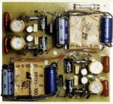
Here are the PCB images and a picture of the finished but unconnected regulator.
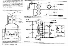
The schematic is in Audio Amateur 1993 volume 4.
Before hooking it up, I found that the positive rails had about a 10X difference in ripple current at the output.
Left channel: +0.032, -0.003
Right channel: + 0.032, -0.005
I was not too concerned about this, but wonder why. I used LM337 and LM337 as regulators, and trim pots for their references.
I set the VR's output voltage at 70 (each rail) , and after installing it and connecting it to one channel, I noticed that the bias current was unstable, even after about 30 minutes. I then replaced R31 and R32 and D15 and D16 with wire as suggested in the AA article (see also post 250). After this, I could not adjust the bias current, and it was about 27mA. I checked voltages at some transitors and they were way off on some legs.
I replaced the Hafler board with a spare (no changes to R31 etc), and lost the bias even faster (in seconds). I checked and recorded voltages at the transistors, and compared them with the table in the Hafler DH220 manual. At least one leg (e, b, or c) was way off for every transistor, and the DC offset was 67. Bias current was again about 27mA. I unhooked the voltage regulator and put in another spare board and the amp was fine.
Pulled transistors (Q1 thru Q13) tested okay with a DMM, but Q1 and Q2 were bad when using a testor based on small lamp bulbs. I did not get a chance to test the others this way. All the diodes, including the zeners, are okay. To be sure, I pulled the zeners and they pass 9.8 volts each. The resistors look okay.
There is not much to hooking the VR up, but for some reason the voltage regulator I made and the Hafler board (PC19c) are not compatible.
Any ideas on what could have gone wrong?
Attachments
Regulator problem?
Hi mmerig
I do not know the schematic in Audio Amateur 1993 volume 4. I f you are afraid of infringement you can probably e-mail it to me.
Without having seen the schematics, have you tested the Regulator output voltages (positive and negative) when installed in the DH-220 amp using the DH-220 transfo before connecting to the PC-19 pbc?
Have you disconnected the DH-220 unregulated supply from the pc-19 pcb when you have connected your regulators pcb?
what is the INPUT voltage or your regulator?
mmerig,
Your description mentions LM337 twice but no LM317. I assume this is just a typo and that you use a pair of + and - regulators.
The PC-19c PCB is used, with only 2 slightly different resistors, in the DH-500 amp. Therefore, it can easily handle the 70 VDC you are trying to give it with your regulator. The original article used 63 VDC as the regulated output but this should not be a problem.
I assume you have double-checked your wiring, etc., etc.
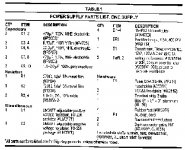
FAB, unless MMERIG beats me to it I will soon post the schematic and parts list for this regulator. Going now to the scanner.
Later................
Dick
Your description mentions LM337 twice but no LM317. I assume this is just a typo and that you use a pair of + and - regulators.
The PC-19c PCB is used, with only 2 slightly different resistors, in the DH-500 amp. Therefore, it can easily handle the 70 VDC you are trying to give it with your regulator. The original article used 63 VDC as the regulated output but this should not be a problem.
I assume you have double-checked your wiring, etc., etc.
FAB, unless MMERIG beats me to it I will soon post the schematic and parts list for this regulator. Going now to the scanner.
Later................
Dick
Thanks for the help, Dick and FAB.
The LM337 listed twice is a typo; there is an LM317 and LM337.
I figured the 70 volts woud be fine, as most of the transistors on the PC19 can handle about 150 volts Vce and Vcb, and its not much higer than the usual rail voltage. The one exception is Q9 (2n222A). but it normally does not see anything beyond 2 volts. Q9 was the first one I checked with the meter, as it sets the bias current. It passed using the DMM, but I tried a new one anyway, and this did not help.
I tested the regulator output voltages (positive and negative) when installed in the DH-220 amp, and they were -70 and +70 from ground. The regulator has its own transformers (FP120-100, see picture in post 271). I did not test the voltage once the wires were connected to the PCB.
The power from the main DH220 transformer goes to the MOSFETS (after going through the rectifier and caps of course) and is disconnected from the PC19 board.
Essentially, the wires at nodes 3 and 10 on PC 19, which originally got to both the MOSFETS and the board, are re-wired so that they just go to the MOSFETs. The output wires of the regulator are then connected to nodes 3 and 10. The regulator's ground wire goes to the star ground of the amp.
The input voltage of the regulator is 120 VAC and it comes off the main switch of the amp.
Fab's modified circuit board
Hi Fab,
I wonder if you would be interested in printing some additional copies of your circuit boards. I would like to try out your mods on a DH200 or 220. Do you consider it nearly done and are you willing to send them out into the world?
Thanks!
Hi Fab,
I wonder if you would be interested in printing some additional copies of your circuit boards. I would like to try out your mods on a DH200 or 220. Do you consider it nearly done and are you willing to send them out into the world?
Thanks!
mmerig,
You have our sympathy. You certainly seem competant and the reason your VR is not compatible seems a mystery to me.
Two more questions, and please realize questions do not impugn your abilities but we all make ommissions now and then. Is the ground of your VR attached to the amp's star ground? Does the PCB with the errant voltages when the VR is attached work OK when re-connected back up in stock condition?
Dick
Hello Dick:
Thanks for being so kind, but questions do not bother me at all.
As for your questions:
The ground wire from the VR was grounded to the star ground of the amp.
The PC19 with the errant voltages does not work (still has errant voltages, low bias current) when connected back up in stock condition. In other words, the VR caused permanent damage.
I plan on replacing bad transistors and see if the repaired board will work in stock conditon.
I think the VR should work, and it seems to be a good design. Why it took so long for the first board to go bad and so little time for the second is puzzling. But I like these kind of puzzles, so I will try and figure it out.
I thought I had done something obviously wrong, but this does not seem to be the case based on feedback so far.
By the way, it is a small world. I used to ski through and climb in he Wallowa Mountans in the late 1970's when I attended the University of Idaho. Passed through Enterprise and Joseph Oregon many times.
- Home
- Amplifiers
- Solid State
- Hafler DH-200/220 Mods