I’m NOT an expert on this amp and have relied HEAVILY on this entire thread and a few very helpful members, two of which are actively assisting Sonic Art.
But I can relate my journey which is not yet over. Two things.
The soft start circuit I got from rsavas is excellent, if he still has some get one.
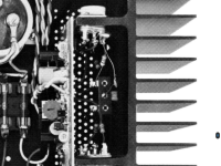
Next, the owner’s manual has a glaring error that definitely bit the previous owner of my DH200. In the pic attached, a zoomed in pic of the finished amp from the owner’s manual Page 18, clearly shows C18 and R40 both connected to the Drain of Q14, while the schematic calls for R40 to be connected to the Gate.
As far as changing the values of C18, and the connection and values of C13 I leave that to the experts. I followed the recommendations of the amp’s designer as covered in earlier posts of this thread.
Good luck.
Jeff
But I can relate my journey which is not yet over. Two things.
The soft start circuit I got from rsavas is excellent, if he still has some get one.
Next, the owner’s manual has a glaring error that definitely bit the previous owner of my DH200. In the pic attached, a zoomed in pic of the finished amp from the owner’s manual Page 18, clearly shows C18 and R40 both connected to the Drain of Q14, while the schematic calls for R40 to be connected to the Gate.
As far as changing the values of C18, and the connection and values of C13 I leave that to the experts. I followed the recommendations of the amp’s designer as covered in earlier posts of this thread.
Good luck.
Jeff
Attachments
mine are pc6, my circuit matches the DH200 manuals. one thing I noticed on the parts list that seems incorrect, Q9 says NP2222 but in the amp it's a 2N 5550.
my gate resistors were on pin 1 gate, but the C18 was a different value to the circuit, and on the gate as well, I replaced with 680pf drain to ground, and replaced C13 390pf gate to source? I believe it is. I used new US made silver mica caps.
I know the DH220 uses 470 and 220ohm gate resistors, with 0.1uf drain to ground on both sides, should we implement this into the DH200 or are other changes needed?
That 5550 is wrong. Never found a part NP2222 but the consensus as I read it is it is either a misprint or an antiquated nomenclature. I replaced my Q9 with a 2N2222.
There is some debate about those cap values, as well as C1, but I view that and the resistor value changes fine tuning, as the last few percent of fidelity and performance. I still have bigger issues with my right channel.
There is some debate about those cap values, as well as C1, but I view that and the resistor value changes fine tuning, as the last few percent of fidelity and performance. I still have bigger issues with my right channel.
Last edited:
well, I thought what if there is leakage from the two on board caps to ground, I fitted panasonic 220uf 100v, and they are bypassed with vishay 0.01uf 100v 1837's. so I unsoldered one leg of the vishay, and now I'm seeing 7mv......
ffffffffffs.... maybe it wasn't me! I am surprised that one of these caps could be bad though...
ffffffffffs.... maybe it wasn't me! I am surprised that one of these caps could be bad though...
Mechanical failure on PCB? Check PCB for hairline cracks in the copper traces. Any aeras where copper traces has lifted from the PCB?
Pay particular attention to aera around Q8 and a any thru-hole/via points on the PCB.
Any aera that has seen excessive heat or has been soldered multiple times? If you find a weak spot, check same aera on opposite channel.
Pay particular attention to aera around Q8 and a any thru-hole/via points on the PCB.
Any aera that has seen excessive heat or has been soldered multiple times? If you find a weak spot, check same aera on opposite channel.
A couple more things to check. Look for a good ground between the heat sink/circuit board assemblies and the main chassis. It relies solely on the contact between them. I removed some of the black oxidation finish and snugged up my mounting screws but others have suggested a good ground jumper wire between the assemblies and the main chassis.
Likewise, the terminal strips that C18 and R40 connect to are grounded just by the contact afforded by the mounting screw. The black finish on the chassis and heat sinks acts as an insulator. Bare shiny metal between them and under the terminal block mounting screw helps.
And there shoukd be tiny insulator orings between the PCBs and the heat sink, under the three PCB mounting screws.
I have been staring at the board for hours today! ") I will go over it again sometime tomorrow, could Q8 be leaky and causing dc?
I will go over it again sometime tomorrow, could Q8 be leaky and causing dc?
on another note, 2N2222, it would appear there is a PN2222, my guess they wrote NP2222 in the manual as the opposite to PN2222. 2N2222A is a higher spec version, I can get them for peanuts but looking at the specs 2N5551 seems a better choice, unless I am missing something important about 2222?
I will go over it again sometime tomorrow, could Q8 be leaky and causing dc? on another note, 2N2222, it would appear there is a PN2222, my guess they wrote NP2222 in the manual as the opposite to PN2222. 2N2222A is a higher spec version, I can get them for peanuts but looking at the specs 2N5551 seems a better choice, unless I am missing something important about 2222?
Hi Sonic Art,
Just a comment. New parts are not always good parts. I have had maybe three bad Japanese transistors from an impeccable supplier I bought from for maybe 20 years, spread out over time. He bought directly from Japan. Too bad he closed shop. These days I test every part before I install it.
PCB traces like to crack right at the pad edge. Very difficult to find. Use your ohmmeter.
Yes, the PN2222 was probably typo'd. 2N2222A is a metal can signal transistor. Nothing really special about them. Check the fT of the 2N5551 along with other parameters before substituting them.
Yes, you are correct. This is a DH-220 thread afterall.Chris maybe you are looking at DH220 specs, mine is DH200
Just a comment. New parts are not always good parts. I have had maybe three bad Japanese transistors from an impeccable supplier I bought from for maybe 20 years, spread out over time. He bought directly from Japan. Too bad he closed shop. These days I test every part before I install it.
PCB traces like to crack right at the pad edge. Very difficult to find. Use your ohmmeter.
Yes, the PN2222 was probably typo'd. 2N2222A is a metal can signal transistor. Nothing really special about them. Check the fT of the 2N5551 along with other parameters before substituting them.
I guess if the 5550 is in a TO-39 package with the heat sink, and the specs are close (I haven’t checked) It should be OK. It’s not what the parts list specifies as you know.
I had fairly high, 30-60mv DC offset when I first acquired mine. I replaced and carefully matched everything on each board, paying particular attention to not just the mirrored trannys but diode pairs like D13/14, 7/10, 11/12, and especially Zeners 8/9. No idea if it helped but now its 6mv and -12mv.
I had fairly high, 30-60mv DC offset when I first acquired mine. I replaced and carefully matched everything on each board, paying particular attention to not just the mirrored trannys but diode pairs like D13/14, 7/10, 11/12, and especially Zeners 8/9. No idea if it helped but now its 6mv and -12mv.
Hi Anatech,Hi,
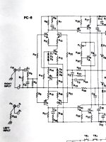
Measure between the two bases, or positive lead on the base of Q3 and the negative lead on the base of Q4. This is with the amplifier running and you'll be measuring in mV (hopefully). This will be DC, not AC.
I’m attaching the input side schematic of the 200 to be certain we are talking about the right transistors.
I am following your advice for Sonic Art and hoping some measurements might lead me to the cure for my problem as well.
To recap, I’m getting a sawtooth on the positive side of a sine wave input only on my right channel, at anything above about 3khz and .1 watts out. New observation is the bias rises significantly with signal while the left channel stays pretty steady with identical input.
Any ideas would be greatly appreciated.
Jeff
Attachments
i measured all diodes and resistors at the beginning, replaced all the resistors on the list of important ones for the differential pairs, replaced the 1ohm 5w with a dale, replaced all caps with 1837 or wima fkp2 except for the mica, I used new silver mica.
I had 7mv right and 40 odd left.
I ordered ic's and matched them on my little transistor kit tester, fitted them to the left Chan and dc came down to 5mv odd.
so I was at 5 & 7, I had one job left, replace the AC wiring on the Thermal breakers as it was tatty. so I unscrewed the right heatsink and moved it out of the way enough to fit the new twisted wire.
while it was out I had been looking for 470uf muse online then I thought to check my BG stash, found a pair of red 470uf BP, that's when I decided to put them in. and that's when I got hit with 250mv on the right.
could be one of the nos caps was leaky they measured good for vloss, capacity and esr.
something i did yesterday dropped it to 10mv, lining up the heatsink on the 2N5415 jumped it back! I had removed this tx earlier and measured hFe58 & 800mv on the meter.
so I am still sitting at 220mv, and haven't looked at it today.
Gone very quiet in here hasnt it...
Today I received a transistor order, some 2N2222's, some 2N5415s (ST Taiwan) and some NOS 2N3440 motorola (this is what the supplier sent me, interesting the motorola measure all over the place, all 4 are quite different from each other).
So following on with my gut feeling from the weekend, I removed the 5415 I was feeling iffy about, and replaced it, DC went from 220mv to 20mv.
Now interestingly the bias went up to 500ma with the new transistor in, I had set it at 290ma while the old 5415 was still in there.
Maybe I disturbed the original transistor and it may have been starting to degrade or had a fault, leaking dc? I dunno, what do the experts think?
I replaced Q9 (2N5550) with a new 2N2222 as per the schematic and will do the other channel once this one is sorted.
So I want to find another 10mv at least, could be the matched pairs are not as close as they could be, I guess I should pull the 470uf cap again to check the pairs balance?
Have resoldered every joint on this board, checked everything, checked continuity across pins to check for track cracks, nothing else appears to be an issue.
One thing I did notice, with a new multimeter (picked up a pair of Micron on special so I had a matched pair for doing bias, dc etc) some of my matched 2.2K and 100ohm resistors are measuring further out compared to my old meter, how much do these resistors affect the balance of the differential pairs and hence dc offset?
Yes the bias pot is back around the original spot (where the paint was put on). With the failing transistor it was up from say 12oclock to 4 oclock to get correct bias, when I measured that IC, hFe was 58, the new ones are around 100 from memory. So I guess this all makes sense?
Today I will sort out the differential pairs, will measure the original Q1/2 Q5/6 and put them back in if they look good, as before this debacle I was seeing 5-6mv DC.
When I measured the diodes at the beginning of the job I noted their figures and they were all very close to each other, none of them were bad or way out.
Resistors, some of the 2.2K were out, someone had put 2.15k in 3 of the 4 spots (R6 R7 R17 R19) The two 560ohm were about 20ohms out, 39K were a few % out, the 22ohm were a little out, and the 100ohm were a few ohms out, replaced all of them as a matter of course.
- Home
- Amplifiers
- Solid State
- Hafler DH-200/220 Mods