So I have a question, the P230 seems to be an under archiver....
P125, output is 1 pair hitachi per channel = 62.5w per channel
200/220/225 output is 2 pairs per = 100-112.5w per
P230 output is 3 pair per? = 115w per
Shouldn’t the output of the P230 be closer to 160w per channel? Is this a design limitation
(ps, voltage, front end, etc) or was thiis purposeful?
The P230 is mainly designed with 3 pair to operate in a professional environment, especially where it may be mounted in a rack with other equipment. Although its heat sink is no larger, the use of 3 pairs adds to reliability. The power transformer is the main limitation on how much power it can put out. I could be wrong, but I think Hafler used the same power transformer on the P230 as on the DH-220. Into a 4-ohm load you may see a bigger difference, since you have 50% more current capability with the P230's 3 pairs for the same amount of voltage drop from the rails.
Cheers,
Bob
Hafler Dh220 intermittent hum
I have a Dh 220 with a Fantasia upgrade I purchased that way. One thing I have noticed is the amp has a hum/vibration ever 45 seconds and last for about 5 seconds it is not audible through the speakers just at the amp . Is this normal I don’t remember the one I had 30 years ago doing that . ?
I have a Dh 220 with a Fantasia upgrade I purchased that way. One thing I have noticed is the amp has a hum/vibration ever 45 seconds and last for about 5 seconds it is not audible through the speakers just at the amp . Is this normal I don’t remember the one I had 30 years ago doing that . ?
A step closer...
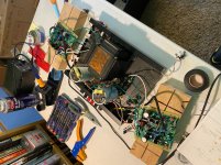
That's where I'm at. Heatsinks with OPS are on the shelf, far away, as I do the AFE settings.
I've got these chassis to AFE connections:
See attached pictures.
All this tells me I should be able to (with ISO and Variac) turn it on to test and set VR1 for each channel.
Do I need a load at the speaker connections for this? I think "no" but it doesn't hurt to ask.
Great minds! Yep, I reverse-engineered it to parse it out and get this far. I also spent quality time with the schematic last night and this morning.It helped me to write out the steps in bullets with my own notes to better understand things.
For setting the IPS bias, I had the AFE boards outside the amp. The OPS boards and MOSFETs were installed but no wires connected to the OPS so no power to the MOSFETs.
That's where I'm at. Heatsinks with OPS are on the shelf, far away, as I do the AFE settings.
For this step, wire up the V+, V- and ground from the power supply to the AFE board. It's important that the ground is connected to the board.
I've got these chassis to AFE connections:
- V+, V-, (connections #3 and #10 respectively)
- The fuse loop (connections #6 and #8)
- The line to speaker out Positive (red, connection #5)
- The line to speaker out Ground (black, connection #7)
This is what you mean by "ground from the power supply" above, yes?
By the way, in my amp this wire literally goes to the reference ground "clothesline" wire between the two power supply caps, and from there to the speaker output. Original Hafler DH-200 wiring has it going from the board to the speaker output and then to the "clothesline". The amp had been modified by Musical Concepts waaaaaay back in the mid 80s before I bought it, used, in 88 or so. So even by Musical Concepts standards, it was probably an early hot-rod. They had bypassed the fuses, added some capacitors to the original amp boards, etc.
By the way, in my amp this wire literally goes to the reference ground "clothesline" wire between the two power supply caps, and from there to the speaker output. Original Hafler DH-200 wiring has it going from the board to the speaker output and then to the "clothesline". The amp had been modified by Musical Concepts waaaaaay back in the mid 80s before I bought it, used, in 88 or so. So even by Musical Concepts standards, it was probably an early hot-rod. They had bypassed the fuses, added some capacitors to the original amp boards, etc.
- The signal connections from amp RCA in (connections #1, #2) This can't hurt.
- All wires from the back of the AFE are taped off to avoid undesired shorts.
See attached pictures.
All this tells me I should be able to (with ISO and Variac) turn it on to test and set VR1 for each channel.
Do I need a load at the speaker connections for this? I think "no" but it doesn't hurt to ask.
Bummer, but no. I do, however, have insulated-handle adjusting drivers. Also, great call with the multimeter mini-grabbers!Hopefully your VR1 and VR2 have the set screws on top (like in the picture above in post #2152). The BOM at the time when I placed the parts order called for the set screws on the side which makes the adjustments more difficult with a higher risk of shorting something with the screwdriver. I've since changed out the VR1/2 with the set screws on top.
Attachments
Left and Right channels dialed in and reading to spec off of R12- because there was no way in the world I was going to get grabbers onto R16!
Right channel read 179mV (target 440mV) and didn't move no matter what I did with VR1. Bad solder joint on middle pin. Fixed and voila!
Time for full assembly and OPS biasing. Very exciting!
Right channel read 179mV (target 440mV) and didn't move no matter what I did with VR1. Bad solder joint on middle pin. Fixed and voila!
Time for full assembly and OPS biasing. Very exciting!
For setting IPS bias, only V+ (#3), V- (#10) and Gnd (#7) need to be connected. The fuse loop (#6 and 8) and speaker out (#5) do not need to be connected. In fact, with the H1 jumper set appropriately, you'll notice in the schematic that the backend of the board is isolated away including the speaker out and fuse loop.
With the VR1 and VR2 set screws on the side, be very carefully not to short something when making adjustments. For example, the 6 pins on the top of the JFET Q10 is near and in-line with the VR2 set screw. I used a piece of electrical tape and covered the JFET as a pre-caution incase I slipped with the screwdriver. I did use a small screwdriver with the shaft insulated with heat shrink.
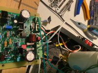
I noticed in your pictures that the amp still has the original Sangamo power capacitors. After 30+ years of operation, these capacitors are out-of-spec limiting the amplifier’s performance. Plus, the original capacitors could fail causing damage to the amplifier and speakers. You can get drop-in replacements that roughly doubles the capacitances which will improve the amp's bass performance and dynamics.
I also noticed in your pictures a box of Winchester shells sitting on your shelf. I shot skeet and trap in my younger days. I own three shotguns which reminds me that I need to get the guns down and re-oil them.
Good luck with your amp build. Bill.
With the VR1 and VR2 set screws on the side, be very carefully not to short something when making adjustments. For example, the 6 pins on the top of the JFET Q10 is near and in-line with the VR2 set screw. I used a piece of electrical tape and covered the JFET as a pre-caution incase I slipped with the screwdriver. I did use a small screwdriver with the shaft insulated with heat shrink.
I noticed in your pictures that the amp still has the original Sangamo power capacitors. After 30+ years of operation, these capacitors are out-of-spec limiting the amplifier’s performance. Plus, the original capacitors could fail causing damage to the amplifier and speakers. You can get drop-in replacements that roughly doubles the capacitances which will improve the amp's bass performance and dynamics.
I also noticed in your pictures a box of Winchester shells sitting on your shelf. I shot skeet and trap in my younger days. I own three shotguns which reminds me that I need to get the guns down and re-oil them.
Good luck with your amp build. Bill.
DH-220C Supplemental Information
I have posted some DH-220C supplemental information on my website at cordellaudio.com. The documents are under the power amplifier tab.
The documents include the following subjects:
1. Expanded circuit description
2. Testing lateral power MOSFETs
3. Complementary JFET matching
Cheers,
Bob
I have posted some DH-220C supplemental information on my website at cordellaudio.com. The documents are under the power amplifier tab.
The documents include the following subjects:
1. Expanded circuit description
2. Testing lateral power MOSFETs
3. Complementary JFET matching
Cheers,
Bob
 !
!Labor pains
I'm still struggling while giving (re)birth to this project.
This shouldn't happen, right? The bulb should stay dim as the capacitors and the rest of the circuit shouldn't be drawing any current- there's no signal, the amp should just be sitting there, power supply caps full, bored, dumb and happy. For example. when the power supply is isolated, it doesn't draw any current and the bulb will stay dim.
Assuming this is the case (the full amp wired up AFE + OPS shouldn't be drawing more current), then something is wrong. But maybe this is where I'm ignorant. Maybe everything is fine, but I don't think so. Caution, etc.
Here's what I think I know is right:
So now I'm trying to think of new things to check:
Thanks. I really want to bring this new/old amp back to life. It will be such a significant step for me in my dreams of building more amps and pre-amps for audio and guitar.
Dennis
I'm still struggling while giving (re)birth to this project.
- I've set the AFE's bias on both channels via VR1- AFE connected to Power Supply. Slam dunk.
- Power supply, despite original caps, is steady Eddie at 60V in isolation and while setting AFE bias. I'll be thrilled to replace the original caps with higher capacitance when the amp is alive.
- I've worked one channel at a time by removing the power supply fuses to the corresponding AFEs
- My problem: when I connect the AFE to the OPS and start testing, I get some unexpected behaviors from the 100w Dim Bulb Tester (DBT). Variac low voltage (say, 60v AC), fine: dim glow from the bulb, power supply caps reading low as well. When I get the variac up to 120v:
- on the DBT for the isolated left channel, I'll get 30v at the power supply and the bulb glowing steadily. I kill within 2 seconds.
- on the DBT for right channel, I'll get a flash, then dim, as should be, but five seconds later, bulb comes back on bright, so I kill it.
This shouldn't happen, right? The bulb should stay dim as the capacitors and the rest of the circuit shouldn't be drawing any current- there's no signal, the amp should just be sitting there, power supply caps full, bored, dumb and happy. For example. when the power supply is isolated, it doesn't draw any current and the bulb will stay dim.
Assuming this is the case (the full amp wired up AFE + OPS shouldn't be drawing more current), then something is wrong. But maybe this is where I'm ignorant. Maybe everything is fine, but I don't think so. Caution, etc.
Here's what I think I know is right:
- The power supply is functional. When powered up and isolated, the caps get to 60v and hold their charge. 10 minutes powered off, isolated and the combined voltage of the caps has leaked from 120v to 100v.
- Wiring between AFE and OPS is correct- am using the fuse loop, saw the note on the Cordell schematic and have wired accordingly.
- The mosfets are good. I have pulled, tested (thanks Bob! Couldn't have been more timely!), replaced with proper thermal paste, new mica isolators, etc.
- Have been over both OPS boards- they're simple enough. Not many parts to screw up. Checked diodes, resistors, re-flowed solder on the bigger capacitors- everything seems solid.
- have been over both AFE boards looking for bad solder joints. Lots of parts there. Can only rely on functional testing to reveal problems.
So now I'm trying to think of new things to check:
- If I were to have AFE hooked to power supply and outputs without OPS, could I monitor a signal amplifying from the AFE? I have an O-scope. Basically to prove the AFEs are doing their job?
- Can I test the power supply direct to the OPS while bypassing the AFE? Essentially connect the V+, V-, and Ground to the OPS (and OPS ground wire to heatsink/thermal fuse connection) and do a DBTest? I htink this would tell me if the OPS is doing its job.
- A basic problem-solving technique is to swap known good for unknown bad. I don't know which of my AFEs or OPSs might be good or bad, but I have to think a combination of the two-each I have would be a safe bet.
Thanks. I really want to bring this new/old amp back to life. It will be such a significant step for me in my dreams of building more amps and pre-amps for audio and guitar.
Dennis
Hi Dennis
Make sure the OPS bias set pot VR2 is initially set to minimum (ccw) to start with. You can verify this by measuring the DCV across the two drive pins.
There is also the OPS bias current monitor test points on the OPS to measure the bias current. With vr2 set to min there should be no current flowing in the ops.
Rick
Hi Dennis,
being a very useful tool without any doubt, it has sometimes to be observed that some amplifiers are getting unstable when fed via a mains bulb tester, most probably due to the increased PSU impedance.
Sadly, I don't know what to do in this case, as I also wouldn't omit a MBT when firing up an amplifier (or any other gear) with either unknown or known problematic anamnesis.
Please follow the bias advice given above. If nothing changes, swap both driver PCB's and observe if the issue follows or not.
Best regards!
I'm still struggling while giving (re)birth to this project.
- I've set the AFE's bias on both channels via VR1- AFE connected to Power Supply. Slam dunk.
- Power supply, despite original caps, is steady Eddie at 60V in isolation and while setting AFE bias. I'll be thrilled to replace the original caps with higher capacitance when the amp is alive.
- I've worked one channel at a time by removing the power supply fuses to the corresponding AFEs
- My problem: when I connect the AFE to the OPS and start testing, I get some unexpected behaviors from the 100w Dim Bulb Tester (DBT). Variac low voltage (say, 60v AC), fine: dim glow from the bulb, power supply caps reading low as well. When I get the variac up to 120v:
- on the DBT for the isolated left channel, I'll get 30v at the power supply and the bulb glowing steadily. I kill within 2 seconds.
- on the DBT for right channel, I'll get a flash, then dim, as should be, but five seconds later, bulb comes back on bright, so I kill it.
This shouldn't happen, right? The bulb should stay dim as the capacitors and the rest of the circuit shouldn't be drawing any current- there's no signal, the amp should just be sitting there, power supply caps full, bored, dumb and happy. For example. when the power supply is isolated, it doesn't draw any current and the bulb will stay dim.
Assuming this is the case (the full amp wired up AFE + OPS shouldn't be drawing more current), then something is wrong. But maybe this is where I'm ignorant. Maybe everything is fine, but I don't think so. Caution, etc.
Here's what I think I know is right:
- The power supply is functional. When powered up and isolated, the caps get to 60v and hold their charge. 10 minutes powered off, isolated and the combined voltage of the caps has leaked from 120v to 100v.
- Wiring between AFE and OPS is correct- am using the fuse loop, saw the note on the Cordell schematic and have wired accordingly.
- The mosfets are good. I have pulled, tested (thanks Bob! Couldn't have been more timely!), replaced with proper thermal paste, new mica isolators, etc.
- Have been over both OPS boards- they're simple enough. Not many parts to screw up. Checked diodes, resistors, re-flowed solder on the bigger capacitors- everything seems solid.
- have been over both AFE boards looking for bad solder joints. Lots of parts there. Can only rely on functional testing to reveal problems.
So now I'm trying to think of new things to check:
- If I were to have AFE hooked to power supply and outputs without OPS, could I monitor a signal amplifying from the AFE? I have an O-scope. Basically to prove the AFEs are doing their job?
- Can I test the power supply direct to the OPS while bypassing the AFE? Essentially connect the V+, V-, and Ground to the OPS (and OPS ground wire to heatsink/thermal fuse connection) and do a DBTest? I htink this would tell me if the OPS is doing its job.
- A basic problem-solving technique is to swap known good for unknown bad. I don't know which of my AFEs or OPSs might be good or bad, but I have to think a combination of the two-each I have would be a safe bet.
Thanks. I really want to bring this new/old amp back to life. It will be such a significant step for me in my dreams of building more amps and pre-amps for audio and guitar.
Dennis
Hi Dennis,
I'm sorry to hear you are having some trouble with the amplifier.
You can very definitely run the AFE by itself as an amplifier by moving the header connector to the TP1 position. This closes the feedback loop from the drivers so everything should bias up correctly. I'm trying to remember in real time if we discussed that technique in the article. When doing that, if power is being delivered to the output stage, the gates of the output transistors for this cautious test should not be connected to the drivers, but rather just to their sources. This keeps the MOSFETs off, so that the only current being drawn will be that of the AFE. Assuming you pass the DBT under that condition, you can then measure all of the voltages in the AFE, but most importantly the voltages at the driver outputs that would normally go to the gates of the output transistors.
Measure the driver - to the driver + voltage as a function of turning the bias pot. turning the pot full CCW should allow that voltage to go very low, probably less than 0.5 V (again, I'm just recalling in real time). Conversely, if you turn the pot clockwise from this position, that voltage should increase. At full CW, you may see 2V or more. The critical thing you are testing here is whether the bias spreader is working properly. If the bias spreader can't get that voltage down to a low enough value at full CCW, then the quiescent current in the output stage under a normal connection may be too high.
Cheers,
Bob
Hi Dennis,
I'm sorry to hear you are having some trouble with the amplifier.
This is how one learns. I'm patient and this process is solidifying and improving my skills. Umm, especially my soldering skills.
Measure the driver - to the driver + voltage as a function of turning the bias pot. turning the pot full CCW should allow that voltage to go very low, probably less than 0.5 V (again, I'm just recalling in real time). Conversely, if you turn the pot clockwise from this position, that voltage should increase. At full CW, you may see 2V or more.
How does 14V V- V+ driver voltage on one AFE grab ya?
So, something was wrong/bad. I started checking off the components near the path from the jumper back, resistors, diodes, etc. and found poor soldering for C16, C16, and one leg of a bjt.
Quite honestly, my soldering skills really did improve during the build- there were a lot of parts to solder- but now I have better solder inspection skills. And even better solder-wick and solder sucker skills. Oh, and some 1.5x glasses from Lowes.
Now The V- V+ driver voltage is .5V.
VR2 was acting funny, I pulled it, verified it functioned through its whole sweep, and put it back in tilted with a little extra access for the adjustment driver.
I'll complete my AFE testing, set the H1 back to the run position, and start my OPS DimBulb check, then bias the OPS. Fingers crossed.
It's a girl!
And I'm live and cooking.
Once I got the AFE board sorted, I was able to move on to the OPS biasing, letting it warm up, re-adjusting.
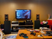
I'm still in the smoke-testing-will-something-blow-up stage, but have hooked it up and given it about 45 minutes of run time / listening time. It certainly passes the old "Oh, I never noticed that before" in my favorite songs test. Noticeably quiet noise floor.
I'm looking forward to it getting a few solid and safe hours under its belt, and then I'll put the cover back on the top and a "C" on the faceplate next to the DH-200 stenciling.
Thank you all for your encouragement and explanations over the last week. I'm very pleased I didn't blow a J or MOS FET. Or anything else, for that matter.
Dennis
And I'm live and cooking.
Once I got the AFE board sorted, I was able to move on to the OPS biasing, letting it warm up, re-adjusting.
I'm still in the smoke-testing-will-something-blow-up stage, but have hooked it up and given it about 45 minutes of run time / listening time. It certainly passes the old "Oh, I never noticed that before" in my favorite songs test. Noticeably quiet noise floor.
I'm looking forward to it getting a few solid and safe hours under its belt, and then I'll put the cover back on the top and a "C" on the faceplate next to the DH-200 stenciling.
Thank you all for your encouragement and explanations over the last week. I'm very pleased I didn't blow a J or MOS FET. Or anything else, for that matter.
Dennis
Attachments
Three weeks later...
Being the learner I am, I managed to blow the mosfets on my left channel while doing some further work. Might have been bad soldering finally ticking the wrong tock, might have been me being foolish enough to (not carefully enough) remove voltmeter probes from the OPS test points while powered up.
Short. Boom. ****. Operation; it takes a very steady hand.
All of which has led me to learn more about testing and patience. And checking and reflowing bad solder joints, bad solder joints, bad solder joints. In the big picture, $70 of mosfets is a relatively inexpensive education.
Here's where I'm at:
New mosfets are in. AFE is VR1 dialed in and testing in range (proper current through R12/24, R13/25). Fully wired AFE to OPS, both channels are driving a clean sin wave test signal into dummy loads, but...
On the channel with the new mosfets, the test point reveals 1.2 mV which is nowhere near the dialed-in goal of 40mV. At 1.2mV, there's no DC offset at the speaker outs, beautiful signal across zero on the scope, amplitude is same as the other channel. If I attempt to adjust VR2 to move the test point measurement toward spec, the DC offset of the output goes south, greatly, and quickly. If I want the output to be -5, -10, -20 volts,
all I need to do is turn VR2.
So... getting to 40mV at the OPS test point is out of the question. Is it okay to run it as it's behaving now with 1.2mV?
Thanks,
Dennis
Hi Dennis. Sorry to hear you’re having more problems. Just a couple of questions. First, with IPS set at 2ma, was the VAS current in the appropriate range per the testing procedure? Second, did you remember to move the H1 jumper back to the normal setting before proceeding to adjust the OPS bias?
Concerning acceptable range for the OPS bias, the targeted 40mv is equal to 400ma total bias current as measured across the OPS 0.1 ohm resistor. This is equivalent to 200ma across each MOSFET pair. This is considered pretty healthy (high) bias to minimize crossover distortion and will make the heat sinks run warmer. A more typical bias current is where the MOSFET thermal coefficient is zero which is normally between 100-150ma bias per MOSFET pair or 200-300 ma total bias for the two pair per channel. MOSFETs do required a certain minimum bias current for proper switching operation and to minimize crossover distortion. I don’t know exactly what that is but I wouldn’t go below say 50ma per pair. Certainly the MOSFETs won’t operate properly at near zero bias current. If the problem is not as simple as forgetting to move the H1 jumper back after setting the IPS/VAS currents, I would start checking for bad solder joints from VR2 forward. Also check that the wires between the AFE and OPS boards are securely connected. Good luck, Bill.
Concerning acceptable range for the OPS bias, the targeted 40mv is equal to 400ma total bias current as measured across the OPS 0.1 ohm resistor. This is equivalent to 200ma across each MOSFET pair. This is considered pretty healthy (high) bias to minimize crossover distortion and will make the heat sinks run warmer. A more typical bias current is where the MOSFET thermal coefficient is zero which is normally between 100-150ma bias per MOSFET pair or 200-300 ma total bias for the two pair per channel. MOSFETs do required a certain minimum bias current for proper switching operation and to minimize crossover distortion. I don’t know exactly what that is but I wouldn’t go below say 50ma per pair. Certainly the MOSFETs won’t operate properly at near zero bias current. If the problem is not as simple as forgetting to move the H1 jumper back after setting the IPS/VAS currents, I would start checking for bad solder joints from VR2 forward. Also check that the wires between the AFE and OPS boards are securely connected. Good luck, Bill.
Last edited:
- Home
- Amplifiers
- Solid State
- Hafler DH-200/220 Mods