Hi Friends,
I have now taken a new repair project of two DNM amplifier. This is a good amplifier as far as 20 Watt RMS per channel and 80 watts for sub is concerned.
Now the problem is one of them has no sound. Display works fine.
The problem began with the subwoofer sounding bad ( continues flapping, if i am not getting the correct word, please forgive) then one day all the channels stopped working.
With some initial trouble shoting i find that the sound signal from the small channels are reaching the relay but the relay is not turning on to connect the speakers.
i have a idea that there will be some kind of comparator ckt which controls the replay and is now protecting the speakers from being damaged.
Please assist, as i have two of them.
The amp is good so i intend to repair it myself.
Any help, any ideas is appreciated.
Thanks,
Hemant.
Attachments
DC voltage at the output is not normal when an amp is turned off.
If the amp is off then the speaker relays must be 'open' so where is your voltage coming from.
Try putting a 10k resistor across each output and recheck the voltage is now zero. It could be stray pickup you are measuring.
You should check the DC voltage at the output of each amplifier before the relay (amp on).
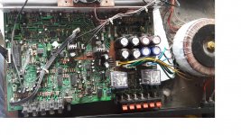
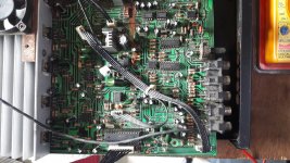
Brown material
If that is glue that has run across the circuitry there sure is a lot of it. Look under the board. I think this is from a leaky capacitor or two.
Look for bulges and soft cases. The large filter caps may be in rough shape. I think the circuitry is acting up and that is why the output relay is open.
How hot did the amps run when operational?
Checking residual voltages when the amp is off isn't really a valid test state.
You need to check that all the DC rails are correct when the amp is ON.
Then check the DC offset at each channels output.
All that brown stuff looks like glue to me. We used to see a lot of that stuff in commercial equipment and its horrible stuff and yes, it can cause issues with high impedance circuitry.
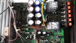
All the power related capacitors were removed and cleaned the pcb as far as possible with little left over of glue.
this part is done. the small regulator capacitors were also cleaned, like 7812, 7912 and 7805.
the input to the lm1785 and dc rails..fixed.
now tracing the relay control ckt.
i will keep posted as i proceed further.
Thanks everyone for their sugesstions and advice ...will definetly be able to solve this one..
thanks again...apriciate it.
Hi,
One of the local suggestions was to clean the PCB with IP solution, so all the power capacitors were removed and the area was thoroughly cleaned, Guess what!!!.. Its working. so the cheat element in my case was the GLUE ( can't even imagine ).
The five channels have been working fine now but the problem it started from, the distorted output is still there.
now i think it needs a scope to check the culprit. i do have a DIY PC scope but though not that accurate..lets see.
Last edited:
Having applied heat could be one clue, as could something physical (you must have at least mauled the boards around a little bit removing the caps).
Poor soldering on those devices on the small heatsinks could be prime suspects, as could poor soldering on those metal oxide resistors... anything that runs hot.
Poor soldering on those devices on the small heatsinks could be prime suspects, as could poor soldering on those metal oxide resistors... anything that runs hot.
hi,
This one was finally completed, both of them.
The problem being an OP AMP 4558, it was used to change the frequency response of the sub.
The input resistor, pot, was out and open i guess provided infinity gain.
Changed it with near term value and that's all. It works like charm.
Thank you all for your valuable inputs, my amp was thoroughly cleaned in the process.")
Will come back soon, with onkyo TXL55...soon.
Regards,
Hemant.
This one was finally completed, both of them.
The problem being an OP AMP 4558, it was used to change the frequency response of the sub.
The input resistor, pot, was out and open i guess provided infinity gain.
Changed it with near term value and that's all. It works like charm.
Thank you all for your valuable inputs, my amp was thoroughly cleaned in the process.
Will come back soon, with onkyo TXL55...soon.
Regards,
Hemant.
- Status
- This old topic is closed. If you want to reopen this topic, contact a moderator using the "Report Post" button.
- Home
- Amplifiers
- Solid State
- DNM Amplifier Repair India