Hello,
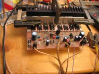
this picture is my "first version" of the Holton SymAmp.
The cooling-angel on wich the output Fet's mounted is 3mm thick.
Is it enought ?
------------------------------
For example the Alps modules have an 6mm thick one.
And holton say's in his manual between 3mm and 5mm
If I touch the Fet's ( driving the amp with an output amplitude of about 25 V and RL = 4 ohm ) they feel realy hot, if you hold your fingers longer than about 2 sec. it hurt.
- The black heat sink is only temporarily, it is too smal but even if the heatsink is at beginning quite cold I mean the Fets are too hot-warm.
will more thick angel improve the cooling significant ?
Greetings Andi
Attachments
Angels have wings...
Hello,
nice work you've done!
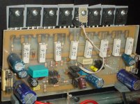
Did you consider mounting the PCB direct to the heatsink without angles?
Be careful on mosfet matching also - keep an eye on the voltage on the source resistor to see if they share the current evenly, otherwise one or some will draw much more current than the others. I experienced that
The pic shows how I did the thing
Cheers
Andrea
Hello,
nice work you've done!
Did you consider mounting the PCB direct to the heatsink without angles?
Be careful on mosfet matching also - keep an eye on the voltage on the source resistor to see if they share the current evenly, otherwise one or some will draw much more current than the others. I experienced that
The pic shows how I did the thing
Cheers
Andrea
Attachments
@ Andypairo
Hello, yes in fact i considered, mounting the devices direct on the heatsink.
But prefer to have an completed modul, wich I'm more flexibly.
I matched the Fet's within 40mV gate threshold, with Holtons method.
It was interesting, the 9240 was easy to get 4 one with near gate threshold ( easy within 10mV ) but the 240 spread much more.
( I have 40 piece 9240 and 40 piece 240 meassured )
@ Magura,
Hello,
I think the angel can be a bit thin than the back of the heat sink.Because he must conducte the heat energy only few mm-1cm but the heatsink have to spread it over an lager area.
------------------------
well in the next day's I'll get my Temperatur sensor's then I will archive better results than getting by touching the things with my fingers")
by the way the Temp sensors I found are interesting ones, cheap and easy tu use. LM 35 ; and LM 335
Hello, yes in fact i considered, mounting the devices direct on the heatsink.
But prefer to have an completed modul, wich I'm more flexibly.
I matched the Fet's within 40mV gate threshold, with Holtons method.
It was interesting, the 9240 was easy to get 4 one with near gate threshold ( easy within 10mV ) but the 240 spread much more.
( I have 40 piece 9240 and 40 piece 240 meassured )
@ Magura,
Hello,
I think the angel can be a bit thin than the back of the heat sink.Because he must conducte the heat energy only few mm-1cm but the heatsink have to spread it over an lager area.
------------------------
well in the next day's I'll get my Temperatur sensor's then I will archive better results than getting by touching the things with my fingers
by the way the Temp sensors I found are interesting ones, cheap and easy tu use. LM 35 ; and LM 335
@ Runebivrin,
Hi,
betwen the Fet's and the side of the angel the Fet's are lieing on is no noticeable temperatur difference.
But betwen the side of the angel at the heat sink and the one with the Fet's is an noticeable difference. But not VERY hight.
The problem is my fingertip not very exactly...
Within the next day's I will populate temperatures here.
I hope you all have the same sunny day,
Andi
Hi,
betwen the Fet's and the side of the angel the Fet's are lieing on is no noticeable temperatur difference.
But betwen the side of the angel at the heat sink and the one with the Fet's is an noticeable difference. But not VERY hight.
The problem is my fingertip not very exactly
... Within the next day's I will populate temperatures here.
I hope you all have the same sunny day,
Andi
tab30 said:
@ Magura,
Hello,
I think the angel can be a bit thin than the back of the heat sink.Because he must conducte the heat energy only few mm-1cm but the heatsink have to spread it over an lager area.
Heat transfer is actually a really simple matter to figure out. Think of the path from the FET to the finns on the heatsink as a pipeline.
Now you have the backside of the fet mating with the angle with grease in between, a fairly big pipe diameter (to keep the analogy going), then you have the angle with very little mass to transfer the heat (its all about mass in the end of the day), thats like taking 100 meters out of the main oil pipeline from Alaska and replacing it with garden hose, very little gets through. Then you have the base of the heatsink, a 10mm plate, that can transfer many times the heat the angle can...the analogy again, after the 100meters of garden hose, you get the main pipeline back....unfortunately the oil seems to get stuck while trying to squeeze through the garden hose.....so the poor americans will have to walk
And your FET's run hot while your heatsink stays cold
Magura
Fact's
This angle I use has an thermal resistance of 0,1 K/W.
I calculated it with this. T from the one side of the angle was 85 C and on the other side it was 65 C and the power disipated by
the Fets was 200 W.
The Fets will die 65 C later at 150 C ... ther is room enough.
now i will try an angle with about the double thikness and look how better it is ...
Andi
Re: Fact's
Hello, I wouldn't feel that comfortable about the temperatures you get. The die of the transistor is much hotter than the case temperature and the 150°C is referred to its temperature.
Starting from 85°C at the case you need to add a temperature given by the product of the thermal resistance junction-to-case of your device (look at the datasheet but in the 0.7-0.8 °C/W range ) with the power dissipated in the device. Also the thermal rise from sink to case has to be taken in account since the temp was taken on the aluminium angle, and usually this interface gives very variable °C/W results, from 0.1 to nearly 1°C/W depending on the insulator.
PS The 200W figure was used only for testing, right? My symamp doesn't burn like that
Cheers
Andrea
tab30 said:This angle I use has an thermal resistance of 0,1 K/W.
I calculated it with this. T from the one side of the angle was 85 C and on the other side it was 65 C and the power disipated by
the Fets was 200 W.
The Fets will die 65 C later at 150 C ... ther is room enough.
now i will try an angle with about the double thikness and look how better it is ...
Andi
Hello, I wouldn't feel that comfortable about the temperatures you get. The die of the transistor is much hotter than the case temperature and the 150°C is referred to its temperature.
Starting from 85°C at the case you need to add a temperature given by the product of the thermal resistance junction-to-case of your device (look at the datasheet but in the 0.7-0.8 °C/W range ) with the power dissipated in the device. Also the thermal rise from sink to case has to be taken in account since the temp was taken on the aluminium angle, and usually this interface gives very variable °C/W results, from 0.1 to nearly 1°C/W depending on the insulator.
PS The 200W figure was used only for testing, right? My symamp doesn't burn
like that Cheers
Andrea
- Status
- This old topic is closed. If you want to reopen this topic, contact a moderator using the "Report Post" button.
- Home
- Amplifiers
- Solid State
- Cooling Angel