Hi Andrew, Jacco and Stuart,
Thanx very much for your replies. Things are much clearer for me now. I think I'm going to try those nice Sankens too.
I hope I don't run in any oscilation problems though... But if it does, the output coils in the schematic by ACD would fix it right?
Jacco: What caps did you replace with the styrolfex ones?
dr.strangelove3 said:if it does, the output coils in the schematic by ACD would fix it right?
Not really, it's there for another reason.
The capacitors are C105 and C106, between base and collector of Q107 and Q108.
Signal transfer in an amplifier needs a minimum phase margin of 60 degrees to remain stable. These capacitors add an additional phase margin to reach that. They lead the phase and are therefore called lead compensation capacitors.(local compensation)
Another way to make a circuit more stable is to slow an entrance signal down, done by placing a filter on the entrance of the amplifier. (global compensation) The English term is lagging, leaping behind, therefore it's called a lag compensation.
note:
I'm likely also the only one using the original Krell schematic devices in the front half of the KSA circuit, the ones i use for Q107 and Q108 are more than 3 times as fast as the ones on the Krell BOM.
You may press the button now, Doc.
Hi Jacco,
I have quessed that the front end of a Lin topology amplifier should be the fastest part and that the speed can be progressively slowed as one moves towards the output stage. This being nescessitated by the availability of medium speed power devices.
Could you elaborate? With particular emphasis on where fast devices should NOT be used and where fast devices are a decided advantage
I have quessed that the front end of a Lin topology amplifier should be the fastest part and that the speed can be progressively slowed as one moves towards the output stage. This being nescessitated by the availability of medium speed power devices.
Your comment seems to imply some theoretical advantage in doing this.I'm likely also the only one using the original Krell schematic devices in the front half of the KSA circuit, the ones i use for Q107 and Q108 are more than 3 times as fast .....
Could you elaborate? With particular emphasis on where fast devices should NOT be used and where fast devices are a decided advantage
Hi Jacco,
I'm sorry for all these novice question..
Pressing the buttun NOW!
I'm sorry for all these novice question..
Where is the output coil then for?jacco vermeulen said:Not really, it's there for another reason.
What devices did you use?jacco vermeulen said:I'm likely also the only one using the original Krell schematic devices in the front half of the KSA circuit, the ones i use for Q107 and Q108 are more than 3 times as fast as the ones on the Krell BOM.
Pressing the buttun NOW!
When the cone of a driver returns to its neutral position the coil of a loudspeaker creates back EMF, which is returned to the amplifier output. To dampen the back EMF the output of the amplifier needs a low output impedance. This is achieved by (parallel) low resistance emitter resistors and for a large part by using feedback (NFB).
Loudspeakers not only act as voltage sources through their coils, they can also have a capacitive nature, act as a capacitor. Some loudspeakers more than others.
A capacitor creates a phase shift between voltage and current, a highly capacitive load can make the output of the amplifier start to oscillate. By placing a coil after the output stage the impedance of the coil becomes higher during capacitive loading at high frequencies, making the total impedance of the output stage higher. This will surpress the influence of the capacitive effect of the loudspeaker and prevent the amplifier from oscillating.
It's safer to put a race car driver in a VW than placing a senior citizen in a Formula 1 vehicle, the elderly one will push up the daisies at the first cornering. (quote from my control systems classes professor, my kind of guy)
A previous stage in an amplifier needs to be faster than the next, otherwise it will not be able to control the devices it drives, leading to high distortion or also to oscillation. Or the next stage needs to be slowed down, like a 30 mph speed limiter on a car to prevent the elderly from massive suicide.
In the KSA front end i have Toshiba 2SA970/2SC2240 and 2SA968/2SC2238. These are all 100MHz devices, and have very flat Hfe curves in the current range they are operated in.
The Onsemi driver devices of the KSA BOM are spec'd at 30Mhz, the transition frequency is determined by the Hfe value. (Ft = current gain bandwidth)
At elevated temperatures the Hfe value of MJE15032/33 devices remains at 100 or above up to an output current of 1 amp, means also an Ft of 100 MHz. The Sanken RET output devices retain their Hfe values up till very high output currents. In effect, the Sankens will not load the drivers the way some other output devices would do at high output currents. Lower Hfe values at high output currents would lead to reduced Hfe values and reduced Ft of the drivers, creating problems.
Changing resistor values changes collector currents, altering the collector current alters transition frequency. Higher collector currents do raise noise.
Markus of the Rookie thread uses Sanken 2SA1216/2SC2922 in the output stage of his design. He is getting very good results with 200 Mhz Toshiba devices in the front end of the amplifier, well worth to follow that thread.
little addition:
It's probably not clear to some what the effect of feedback is on the output impedance (and damping factor) of the output stage.
The negative feedback not only corrects the inperfection of the voltage gain of a circuit, the momentary difference between input voltage and supposed to be output voltage.
Back EMF returns a voltage(difference) to the output of the amplifier. The negative feedback resistors return the scaled correction voltage back to the differential entry stage of the circuit. The voltage difference created by back EMF thereby creates a response through the NFB of the output stage to correct the deviation, the output stage counterbalances back EMF by an output voltage of different signature. That is why higher NFB raises the damping factor of output stages, higher feedback values means faster damping response.
I believe Nelson Pass stated he never had a need for additional features on his output stages, means you can get an output stage stable enough to handle capacitive loads without gadgets.
4 Channel KSA-50 finished
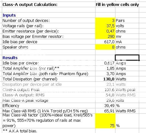
Finished my 4 channel KSA-50...I biased each channel to 290 MV...thats with 3 pair MJL21193/94 per channel with .47 ohm emitter resitors ...is my math on this correct for 50 watts channel?
Thanks to all who contribute to DIY and this thread !
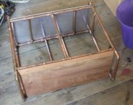
Here are a few pics for the interested:
http://img231.imageshack.us/my.php?image=dscn12249yg.jpg
http://img60.imageshack.us/my.php?image=dscn12304et.jpg
http://img230.imageshack.us/my.php?image=dscn12354rg.jpg
Finished my 4 channel KSA-50...I biased each channel to 290 MV...thats with 3 pair MJL21193/94 per channel with .47 ohm emitter resitors ...is my math on this correct for 50 watts channel?
Thanks to all who contribute to DIY and this thread !
Here are a few pics for the interested:
http://img231.imageshack.us/my.php?image=dscn12249yg.jpg
http://img60.imageshack.us/my.php?image=dscn12304et.jpg
http://img230.imageshack.us/my.php?image=dscn12354rg.jpg

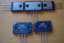
Here's a picture to demonstrate the case size and cooling ability of large size RETs. The one on the left is a 200 watt TO264 MJL4281.
The Sanken 2SA1294 has the same die as the 2SA1295 but in a single bolt TO3P package(or MT100). The 2SA1295 is rated at 200 watts and 17 amps, the 2SA1294 at 130 watts and 15 amps, all other parameters are identical. TO3P device size is identical to TO264.
6 Sanken (150watt type) RETs easily replaced 12 BD911-BD912s(90watts) on a class A amplifier, with better overall performance figures.
Here´s what someone experienced with the TO3P type 2SA1294/2SC3263, you can imagine the MT200 packaged versions to do better =>
www.diyaudio.com/forums/showthread.php?postid=451766#post451766
Best RET's i've seen/used were the 2SA1094/2SC2564(Ft :70/90 MHz) Electronique Diffusion in France sells a number of difficult to find devices, they have stores in Northern France, i periodically visit their store in Lille.
btw: C105 and C106 on the Vas devices are called Miller caps. They act as a capacitance multiplier of the Vas devices. With the current resistors they act as RC filters and limit the bandwidth and slewrate of the amplifier. In this sense they are called lag compensators. The Vas is the slowest stage of the amplifier. By using larger Miller caps the amplifier becomes more stable, but at the cost of speed and bandwidth.
Attachments
Hi Jacco,
Thanks for the pictures. A few days ago I ordered a few parts in the to264 and the MT200 housing, just to see and feel the difference.
I have also ordered some of the faster 2sa970 and 2sc2240.
I am also trying to understand something of the effects regarding the use of devices with higher Ft.
Looking at the other Krell schematics there is something that puzzles me. The KSA-100 and KMA-160 also use VN0210N5/VP0210N5 Mosfets and the KMA-160 also the 2SK163/2SJ44 JFets.
So tryning to learn something, but I can't find the Ft for these devices in the datasheets. Do Mosfets and JFets have no Ft?
The Ft of a BJT is determined by Hfe, the transition frequency Ft is where Hfe drops to unity gain. For BJT devices Hfe increases with higher output current, and then starts to drop.
Mosfets do not have an Hfe, there is no current going through a base. The base of a Mosfet has a metal oxide layer, Mosfets are voltage driven. Current is necessary for a mosfet to charge or discharge the gate(base) fast enough. Mosfets do have an Ft, but much higher, most of the really fast amplifiers were mosfet designs.
Spectral is the most famous, with power amplifier designs that had a bandwidth of 1 MHz.(tested even higher)
You may want to compare the original Krell schematic Bra posted with the revised one. The Toshiba 2SA968B/2SC2238B i use for the Vas stages have a minimum Hfe of 200, MJE1503* are good for 50 minimum. (i used the lower Hfe O-version first)
The second Vas stage emitter resistor of the original is 100 Ohms, of the clone it is 150.
Lack of linearity is the cause of distortion.
Hfe changes with current, frequency, and temperature.
Collector current at given voltage changes with temperature.
Ft is a current-gain-bandwidth figure, 100 MHz Ft at 100 Hfe translates to 1 MHz.
A Sanken output device with an Ft of 60 MHz doesn't mean you can make it put out 60MHz with an Hfe of 100 at full power.
At 4 amps out a 2SA1216 has an Hfe of 70 and an Ft of 42 Mhz, it can do a 600 Khz signal at 4 amps out.
At 60 Mhz it puts as much current out as is put in the base.
They arrived today and I shipped approx half of them before I ran out of envelopes 
I'll try to get the rest out today, if not then first thing monday.
Some "but"s though. Some missinformation on the postalservice homepage caused some error in shippingcost so insted of padded envelopes there are plain envelopes and padded badges. A small thing but I just wanted you to know.
The other thing is that I ofcourse managed to order two small badges with only the Krell-logo extra and thus two less with the "KSA-50 Clone". Because of this I removed my own and plan to send it along with the prototype I recieved.
")
- Home
- Amplifiers
- Solid State
- Krell KSA 50 PCB